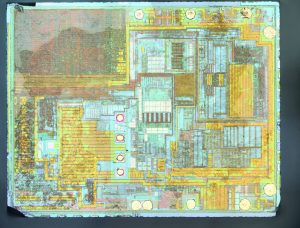
I’ve previously written on what lies within the package of the DS3231 real-time clock, a temperature-compensated 32.768 kHz crystal oscillator and RTC. I’ve also discussed the difference between the crystal-based DS3231 and the MEMS oscillator-based DS3231M. Now it’s time to look within the DS3231M.
This particular chip was a free sample from Maxim Integrated (thanks, guys!) direct from their factory/distribution system and so is guaranteed to be authentic. Unlike my previous attempt (which involved physically grinding the package down and delicately picking out the silicon die and crystal), this chip I dissolved in hot nitric acid in a fume hood for about 30-45 minutes. I then washed it with deionized water followed by an isopropanol rinse. Unfortunately, this process left the die either with some sort of residue, or incompletely etched certain parts, so there’s what looks to be “water marks” around the chip (this is distinctly noticeable in the large block in the top-left).
The image is a composite. To make it, I first focus-stacked (using PICOLAY) a dozen or so images that cover the same, small area of the chip with different depths of field in each photo. I then moved the field of view to a neighboring region of the chip and repeated the process. The focus-stacked images were then stitched using the Microsoft Image Composite Editor resulting in a single large, high-resolution image whereby everything is (I hope) in focus.
Unsurprisingly, the die layout is completely different from that of the DS3231, presumably due to the differences in driving and collecting signals from a crystal oscillator and a MEMS oscillator. The crystal-based DS3231 switches in or out tiny on-die capacitors to slightly change the frequency of the oscillator to compensate for variations in temperature while the DS3231M uses “digital adjustment controller logic” to adjust the final 1 Hz output that one can access on the SQW pin and which also is fed into the internal clock circuitry.
I’m uncertain if the MEMS oscillator is supposed to be on the die (if so, I didn’t see it — perhaps readers might have better luck) or in the package itself (though I didn’t see it when I picked the die out of the acid, but there was a lot of gunk from the dissolved package).
What’s the deal with the enormous metal section in the lower-middle-left? I haven’t the foggiest.
Any thoughts or ideas? If you have any insight I’d love to hear it.