My DS3231 test setup

I wanted to test several DS3231 (M and non-M variants) boards for drift, so I mounted eleven of them (including one known-genuine DS3231M, the leftmost one on the front row, with a green bodge wire) to a breadboard, connected a regulated power supply (AMS1117) at 3.3V to both power rails, and made sure they all worked.

Eleven DS3231 (including 3 M variants) on a breadboard for testing.

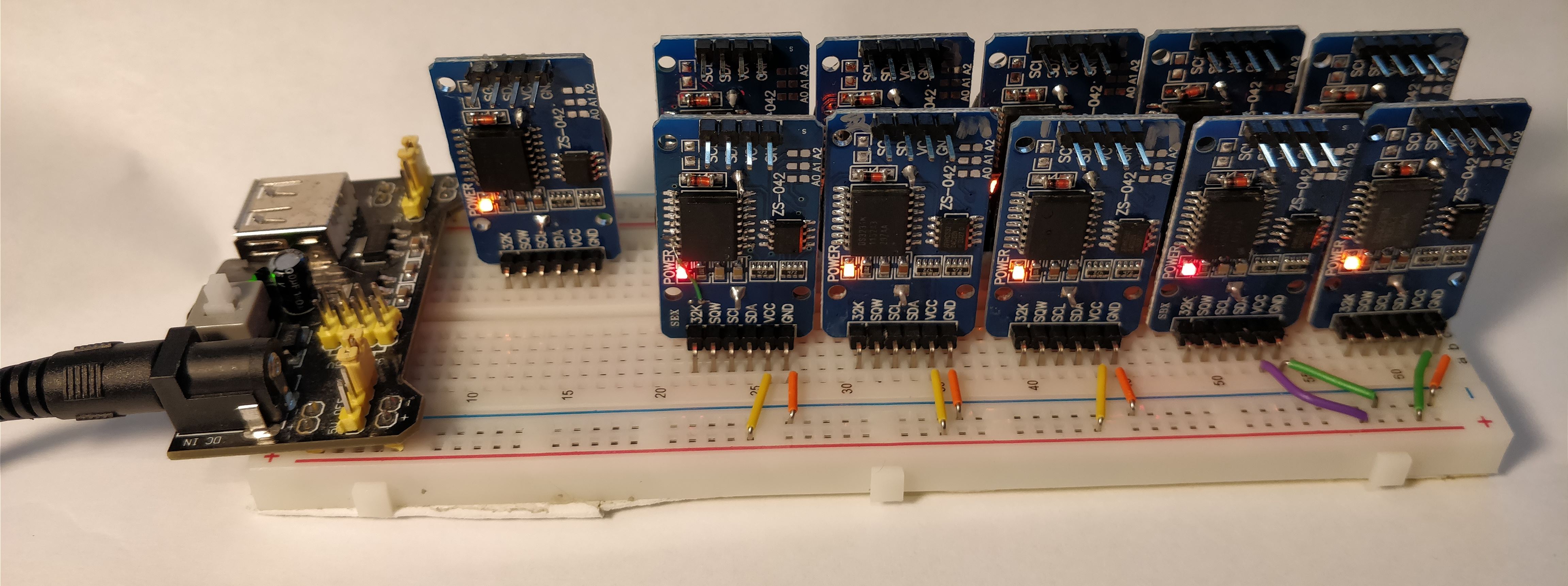
Yup, they all work. The boards have either orange or red LEDs, so they emit a pleasing glow at night that prevents me from crashing into things in my office at home.

Why use 3.3V? One, it makes interfacing with the 3.3V I2C pins on a Raspberry Pi easy since I don’t need a level-shifter, and two, it minimizes drift in the event that I need to disconnect the power and have the clocks run on their coin cell backups. The CR2032 batteries have a nominal voltage of 3.0V, but all currently measure 3.3V (they’re brand-new, Energizer-brand cells from Digi-Key). The DS3231 datasheet says the drift can change by up to 1ppm/volt, so I want to minimize the voltage difference between the normal power supply and the coin cells.

To ease the comparison of drift, I want to ensure all the clocks start counting at the same moment. I could set them all one at a time, but this is complicated because (a) I don’t have an I2C multiplexer chip, and (b) setting them sequentially means they’re not all set at the same moment. It probably wouldn’t matter much in the long run, but it would make me happy to set them at the same time.

The DS3231 modules all have the I2C address of 0x68, and it cannot be changed. Normally, you cannot have multiple chips with the same address on the same I2C bus, as they’ll talk all over each other and the resulting signals will be garbage.

Fortunately, we don’t need the DS3231s to talk; they need only listen to the master and make the appropriate ACK/NAK signals as needed. They should all send the same ACK/NAK signals at the same time so, in theory, there shouldn’t be a problem.

Next, we need to worry about bus current. Each module has a 4.7k ohm pull-up resistor for the I2C bus. With eleven modules, that means the effective pull-up resistance is ~430 ohms. At 3.3V working voltage, a device would need to sink nearly 8mA to correctly signal a logic low. The Raspberry Pi I have can sink 16mA per GPIO pin, so that’s fine. The DS3231 datasheet says the IOL is 3mA, though I spoke with an engineer at Maxim Semiconductor and they said the absolute maximum current the process used on the chips is 10mA. 8mA is close to that limit, but the current would hopefully be spread across many devices and would only be for a few microseconds in total, so it should be fine.

I was satisfied I wasn’t going to blow anything up (and if I did, replacements are cheap), so I connected all eleven modules in parallel to the same I2C bus and commanded them to set their date and time to an arbitrary date in the past. If this was successful, I could send a command to read the time and, if all the modules had the same time, it would come through without an error. If things didn’t work, garbage would come in and I’d have to check them individually for the correct time. One read to all of the devices simultaneously, and I had valid data for that arbitrary time and date. Excellent. It worked!

Using the Raspberry Pi synchronized to a local NTP server (another Raspberry Pi running NTP with a GPS reference clock) within less than a millisecond, I send the command to set the date and time on all the modules to the current time on Friday 8 Sep 11:18:16 UTC 2017 (unix time: 1504869496). Reading the date and time from all the modules confirms they all have the correct date and time with no errors.

Now I’ll let them run for a while to see how they drift. A few have hand-tuned aging registers, so they should hopefully drift less than the others, while others use the default aging register of 0.


MAX31855 Temperature Linearization

Thermocouples are amazing temperature sensors. They’re simple (just two wires!), cover a wide range of temperatures, have no moving parts, are incredibly robust, and are easy to use and deploy.

However, the temperature-dependent voltage they produce is very small (for example, the common K-type I refer to throughout this post produces a nominal 41.276μV/°C) and they require temperature compensation if their “cold junction” (the end not being used to measure something and which is not necessarily colder than the sensing end) is not at exactly 0°C, so purpose-built chips like the MAX31855 are made to amplify the very weak signal, measure the cold junction temperature and apply the necessary compensation, digitize the readings, and provide the result over a digital interface like SPI.

Breakout boards, like this excellent one from Adafruit, combined with their tutorial and Arduino library, make using the MAX31855 simple.

Very cool.

However, the MAX31855 has one glaring issue: it assumes the temperature-to-voltage relationship (the “characteristic function”) of the thermocouple is linear over its entire -200°C to +1,350°C temperature range. It isn’t.

In fact, for K-type thermocouples, the characteristic function goes highly non-linear at very low temperatures. Ideally, E(-100°C) would be -4.128mV. Instead, it’s -3.554mV according to the NIST tables. E(-200°C) should ideally be -8.256mV, but it’s actually -5.891mV. Yikes!

Characteristic function for selected thermocouple types at low temperatures.

At positive temperatures, K-type thermocouples are significantly more linear, with <1% error at 1,000°C and ~2.2% at 1,350°C. Although the MAX31855 works across the full range of temperatures for K-type thermocouples, it’s obviously designed to be mainly used in the linear, positive-temperature territory.

Part of my work involves measuring things at both liquid nitrogen temperatures (-195°C) and at very high temperatures (200-1,000°C). I can tolerate an error of a few degrees, but when I immersed a type-K thermocouple in liquid nitrogen and connected it to a MAX31855, the reported temperature was only -130°C.

Not good.

Fortunately, the good folks at Maxim Integrated provided me with a handy guide on how to properly correct the non-linearized output of the MAX31855. It’d be easy if the chip would provide us the actual thermocouple voltage it measured, but it doesn’t (darn!), so we need to reverse to calculations it does internally to derive the measured voltage so we can apply the corrections.

Let’s walk through how to do so in 5 easy steps. We’ll use the example values from the guide: the true temperature being measured is -99.16°C, the cold junction temperature is 22.9375°C, and the non-linearized cold junction-compensated temperature (“raw”, using the guide’s term) output by the MAX31855 is -84.75°C.

  1. First, subtract the cold junction temperature from the raw temperature:-84.75°C – 22.9375°C = -107.6875°C
  2. Next, calculate the thermocouple voltage corresponding to that temperature if we assume the thermocouple was perfectly linear and E(T) was 0.041276mV/°C:-107.6875°C * 0.041276mV/°C = -4.44490925mV
  3. This part’s a bit tricky: we need to calculate the equivalent thermocouple voltage (“E”, in mV) of the cold junction using the cold junction temperature reading from the MAX31855, the NIST temperature-to-voltage coefficients (c0, c1, …, cn and a0, a1, and a2). The an values are only used for positive temperatures. For some reason, Maxim uses different letters for the coefficients than NIST, so keep that in mind. Here’s the formulas we need:For temperatures <0°C:$latex E = \sum\limits_{i=0}^10 c_i \cdot t^i$For temperatures >0°C:$latex E = \sum\limits_{i=0}^9 c_i \cdot t^i + a_0 \cdot e^{\left(a_1 \left(t – a_2\right)\right)^2}$

    Where t is the temperature of the cold junction. The coefficients are different for positive and negative temperatures, so be sure you’re using the right values from the table.

    The example in the guide has the cold junction near room temperature, so we need to use the equation for positive temperatures. I’m rounding the coefficients here for readability, but you should use the full ones in your code.

    $latex E = -0.176\times10^{-1} \cdot 22.9375^0 + 0.389\times10^{-1} \cdot 22.9375^1 + 0.186\times10^{-4} \cdot 22.9375^2 – 0.995\times10^{-7} \cdot 22.9375^3 + 0.318\times10^{-9} \cdot 22.9375^4 – 0.561\times10^{-12} \cdot 22.9375^5 +0.561\times10^{-15} \cdot 22.9375^6 – 0.320\times10^{-18} \cdot 22.9375^7 + 0.972\times10^{-22} \cdot 22.9375^8 – 0.121\times10^{-25} \cdot 22.9375^9 + 0.119 \cdot e^{\left(-0.118\times10^{-3} \left(22.9375 – 0.127\times 10^{3}\right)\right)^2} = 0.916753\textrm{mV}$

  4. The next step is easy: just add the cold junction equivalent thermocouple voltage you calculated in step 3 to the thermocouple voltage calculated in step 2:-4.44490925mV + 0.916753mV = -3.528157mV
  5. The result of step 4 is the linearized thermocouple voltage. Now we just need to convert that voltage to a temperature. Fortunately, NIST has done the hard work for us and provided us with an easy equation:$latex T = d_0 + d_1 \cdot E + d_2 \cdot E^2 + d_3 \cdot E^3 + … + d_n \cdot E^n$, where T is the corrected, linearized temperature in °C, dn are the inverse coefficients given at the bottom of NIST tables (note: there’s three groups of inverse coefficients, each corresponding to a different temperature and voltage range — be sure to use the right one!), and E is the sum of the two thermocouple voltages you calculated in step 4.$latex 0 + \left(2.52 \times 10^{1} \cdot -3.528157\right) + \left(-1.17 \times 10^{2} \cdot -3.528157^2\right) + \left(-1.08 \times 10^{3} \cdot -3.528157^3\right) + … + \left(-5.19 \times 10^{8} \cdot -3.528157^8\right) = -99.16^{\circ}\textrm{C}$

That’s it!

I’ve put up some MIT-licensed example Arduino code  at my GitHub repository that will perform the necessary corrections. It uses the Adafruit MAX31855 library to talk to the chip, though it should be easy enough to adapt if you’re not using that library or are developing for another platform. Any suggestions or improvements are welcome!

Fellow Adafruit forum member jh421797 has also made some handy code for accomplishing the same result. It, as well as an earlier version of my code (my GitHub repo has the latest version), is available on the Adafruit site.

Fortunately, Maxim has now released a worthy successor to this chip: the MAX31856 improves on the MAX31855 by adding 50/60Hz line frequency filtering to remove noise induced by power lines, a 19-bit (vs 14-bit for the MAX31855) analog-to-digital converter, support for many different types of thermocouples using a single chip (vs needing to buy a different chip for different types), and, critically, automatic linearization using an internal lookup table.

Interfacing with the MAX31856 is slightly different than the MAX31855, but Peter Easton has released an excellent Arduino library for it. He also makes and sells excellent, US-made breakout boards for the MAX31856 in both 5V and 3.3V editions. I highly recommend them. (Full disclosure: he sold me a few at a discounted rate for testing and evaluation. See my brief review here.)