Maxim Integrated has a handy website of various products that have reached the end of life (EOL), and break out some products into categories such as “not recommended for new designs” (in that they’re planning to be discontinued in the near future) and “no longer available”.
It turns out that several DS3231 variants are on the list at the time of this post:
Status
Part Number
NRND
DS3231MZ/V+
NRND
DS3231MZ/V+T
NLA
DS3231N/DIP
NLA
DS3231S
NLA
DS3231S#-W
NLA
DS3231S#C14
NLA
DS3231S/T&R
NLA
DS3231S/T&R#C15
NLA
DS3231SN
NLA
DS3231SN-C16
NLA
DS3231SN/T&R
Uh-oh. Does this mean the DS3231 is no more, as Ed Mallon mentions in an addendum to his post?
I contacted Maxim and inquired what was going on, and the response was that the non-RoHS versions (e.g. with lead solder) are being discontinued, while the RoHS-compliant versions (designed by a “#” mark, like “DS3231SN#”) are still being actively produced and are recommended for use in new designs.
The RoHS-compliant versions have identical timekeeping specifications as the non-RoHS verisons.
On July 31st 2017 at 2:31:00am CEST, I synced the time on a DS3231N to GPS via NTP (+/- a few microseconds). I had previously tuned the clock by setting the offset register to 0x09 and verifying the stability against my Trimble Thunderbolt using an oscilloscope.
At the time I set it, my oscilloscope-and-Thunderbolt measurements indicated it had a short-term stability (over the course of a few minutes) of 1.38 ppm, which is within the +/- 2 ppm specs. I then removed the module (it had a coin cell battery backup) from the NTP server Raspberry Pi that had set it and transferred it the Raspberry Pi I have setup as a strictly “offline” system to store some PGP keys away from the prying eyes of the internet.
Since this system would never see the internet, having an accurate RTC meant that I wouldn’t need to set the system clock from my wristwatch when I turned it on — that’d be inconvenient.
Slightly over three years later on August 12th 2020 I turned on the offline Pi and logged in via a serial link (no network connectivity at all) to the terminal. At 11:18:47 PM PDT as measured by my GPS-backed NTP server, I compared the time between the NTP server and the Pi. Adjusting for time zones, the offline Pi reported the time as 11:19:13 PM, or 26 seconds fast.
95,838,467 seconds of actual time elapsed between the two measurements and the clock only gained 26 seconds. That’s a long-term stability of 0.27 ppm.
I’m impressed: considering the clock was running off a CR2032 battery as opposed to regulated power from the Pi (which had not been plugged in at all during that time). During this time it had undergone several flights and car journeys as part of an international move, and had not been in any sort of specifically-regulated thermal environment (e.g. ordinary residential rooms).

This particular chip was a free sample from Maxim Integrated (thanks, guys!) direct from their factory/distribution system and so is guaranteed to be authentic. Unlike my previous attempt (which involved physically grinding the package down and delicately picking out the silicon die and crystal), this chip I dissolved in hot nitric acid in a fume hood for about 30-45 minutes. I then washed it with deionized water followed by an isopropanol rinse. Unfortunately, this process left the die either with some sort of residue, or incompletely etched certain parts, so there’s what looks to be “water marks” around the chip (this is distinctly noticeable in the large block in the top-left).
The image is a composite. To make it, I first focus-stacked (using PICOLAY) a dozen or so images that cover the same, small area of the chip with different depths of field in each photo. I then moved the field of view to a neighboring region of the chip and repeated the process. The focus-stacked images were then stitched using the Microsoft Image Composite Editor resulting in a single large, high-resolution image whereby everything is (I hope) in focus.
Unsurprisingly, the die layout is completely different from that of the DS3231, presumably due to the differences in driving and collecting signals from a crystal oscillator and a MEMS oscillator. The crystal-based DS3231 switches in or out tiny on-die capacitors to slightly change the frequency of the oscillator to compensate for variations in temperature while the DS3231M uses “digital adjustment controller logic” to adjust the final 1 Hz output that one can access on the SQW pin and which also is fed into the internal clock circuitry.
I’m uncertain if the MEMS oscillator is supposed to be on the die (if so, I didn’t see it — perhaps readers might have better luck) or in the package itself (though I didn’t see it when I picked the die out of the acid, but there was a lot of gunk from the dissolved package).
What’s the deal with the enormous metal section in the lower-middle-left? I haven’t the foggiest.
Any thoughts or ideas? If you have any insight I’d love to hear it.
It’s been just under 5 months since I simultaneously synchronized ten DS3231/DS3231M RTCs as part of a long-term experiment to measure their drift. Of the ten, seven are crystal-based DS3231 chips, while three are DS3231M chips. Since they’re all on the same breadboard connected to the same power supply, all of them have been subject to the same physical conditions of temperature, movement, voltage, etc. insofar as I can control for them in my apartment.
In the table below “Number” is the identifying number of each chip I arbitrarially asigned to uniquely identify each one, “Type” refers to its type (all the DS3231 modules are marked as the wide-temperature-range SN type, while the DS3231Ms are listed as M. The official DS3231M chip (#2) I received directly from Maxim is marked with an asterix.), “Offset” is the aging offset in register 0x10 expressed in decimal form, “PPM” is the stability in parts per million, and “Drift” is the number of seconds the clock has drifted since the start. For both the PPM and Drift columns, a positive value indicates that the RTC has run faster than the NTP-synchronized system clock while a negative value indicates the RTC has run slower than the system clock.
All results were collected over a 26 minute period starting 12904549 seconds after the clocks were first synchronized. Each clock was measured three times and the resulting values averaged and rounded to two decimal places. Keep in mind that this dataset consists of just two data points (zero drift at the start, and the measured drift now) for each clock: unlike Dan, who continuously collected data and made many nice graphs, I set the clocks and essentially ignored them for five months.
Anyway, I digress. Here’s the results:
Number	Type	Offset	PPM	Drift
0	SN	-6	0.19	2.46
1	SN	0	-0.69	-8.96
2	M*	0	-1.62	-20.85
3	M	0	-3.06	-39.54
4	M	0	-2.76	-35.65
5	SN	0	0.16	2.07
6	SN	0	0.01	0.10
7	SN	-15	0.33	4.32
8	SN	0	0.08	0.98
9	SN	0	-0.05	-0.60
Some commentary, bullet-pointed for your reading pleasure:
All clocks are within their advertised tolerances (2 ppm for the crystal-based clocks and 5 ppm for the MEMS-based clocks).
Five of the seven crystal-based DS3231 chips run fast, while two run slow. All three of the MEMS-based DS3231M chips run slow.
Clock #6 has essentially no drift whatsoever. There’s nothing particularly noteworthy about it: just luck of the draw.
The Raspberry Pi used to set the clocks in September was also used to measure the offset today. It has run continuously since the clocks were set, and has been synchronized continuously to another Raspberry Pi (+/- 0.1 ms), which was in turn synchronized to GPS using a Motorola Oncore UT+ receiver (+/- 150 ns). Time errors on the Pis are negligible.
I have two PCA9548A I2C switches that allow me to wire up all the clock chips and switch between them using software commands rather than needing to physically move wires around. This makes life easy.
At the start of the measurement, I had observed each of the clocks’ outputs using my oscilloscope and compared them to a GPS-synchronized PPS signal. Clocks #0 and #7 drifted faster than the others but were still within the advertised specs (unfortunately I didn’t write down how fast they were drifting and have since forgotten). I adjusted the aging register until the short-term drift was minimal; the results are acceptable, though I note they drifted the most of any of the crystal-based clocks.
All ten clocks are part of a cheap module available on eBay from various Chinese sellers. The module comes with either a DS3231 or DS3231M chip (the sellers don’t sort them so you can get either type at random) of various vintages. The oldest I’ve seen is from 2006. None of the chips seem to be new, with various smudges and wear visible on the face of the chip, so they’re likely pulled from old equipment and reused on these boards. Even so, they work well.
Each board also comes with a 24C32A I2C EEPROM, which is nice, but not strictly necessary. I use them for storing the aging offset in case I remove the backup battery and want to tune it again without using the oscilloscope.
The boards also come with a holder for a backup coin cell battery. Critically, the boards are also wired with a 2N4148 diode and a 200-ohm series resistor feeding the positive terminal of the battery, presumably for use with a (not included) LIR2032 rechargeable coin cell. If you use a non-rechargeable CR2032 coin cell you must remove either the diode or resistor or else the circuit will try to charge the coin cell battery, which can damage the battery. I’ve removed the battery holder entirely from one or two other test boards and the charging circuit works well to charge a backup supercapacitor, but the charging circuit must be removed or disabled if you use non-rechargeable coin cell batteries.
The data here is just a brief summary; I have more detailed data in a spreadsheet that’s available upon request.
My ensemble of DS3231 and DS3231M RTCs has been running since early September 2017 and I’m looking to start gathering data on their performance in the near future. Thus, I’ve taken one of the DS3231 RTCs from the ensemble (leaving ten) and done some experiments with it to figure out how best to read the time from the clock chips at the highest precision I can using a Raspberry Pi.
This is complicated by three issues:
Although the DS3231 RTC has an internal 15-bit counter that counts individual crystal ticks, that counter is not accessible by the user. Instead, we can only access the timekeeping registers with a precision of one second.
Due to weirdhistoricalquirks that trace back to the original MC146818 RTC used in the first PC/AT standard, the hwclock utility sets the RTC so there’s a half-second difference between the system clock and the RTC.
With the reference NTP daemon running on a stock Raspbian system, the kernel enters an “eleven minute mode” where it will periodically set the RTC’s clock to the NTP-synchronized system clock. This is undesirable, but turning it off requires recompiling the kernel and I’m lazy.
First Issue
To address the first issue, I use the hwclock -c command, which repeatedly reads the timing registers on the RTC until the second changes. With the help of an oscilloscope and logic analyzer, I’ve confirmed that the seconds register (hex value 0x0, or “00h” in the notation the datasheet uses) is updated on the next read after the 1 Hz square wave output falls.
It’s worth quoting this part of the DS3231 datasheet:
On an I2C START or address pointer incrementing to location 00h, the current time is transferred to a second set of registers. The time information is read from these secondary registers, while the clock may continue to run. This eliminates the need to reread the registers in case the main registers update during a read.
This means that nothing weird will happen if the 1 Hz counter ticks in the middle of a read and the next read from the seconds register after the tick will have the latest value. Perfect. This means we can mark the new second with a precision of +/- 1 I2C read packet, which is ~1 ms when using hwclock to read the data. Not bad.
Second Issue
For the second issue, we need to account for a half-second offset between the system clock and the RTC. If we let the kernel automatically set the RTC using the “eleven minute mode”, the RTC is a half-second ahead of the system clock. The output of hwclock -c looks like this:
That is, the RTC is 0.486747 ahead of the system clock. The reported precision is far too high: I’ve measured a difference of 3-4 milliseconds between the value reported by hwclock and difference between the RTC’s 1 Hz pulse and the UTC-aligned one-pulse-per-second (PPS) signal from a timing GPS receiver.
However, if we set the RTC manually using hwclock -w,the system clock is a half-second ahead of the RTC (at least until the eleven minute mode resets the RTC). Here’s an example:
Keep this in mind if you decide to do a similar test. For consistency, I used hwclock -w to set all the clocks in the ensemble simultaneously. One nice thing about the DS3231 and DS3231M is that it resets its internal 15-bit fractional seconds counter whenever the seconds register is written, so once set you only need to account for the half-second offset and not any leftover fractional seconds. (See the “Clock and Calendar” section of the datasheet: “The countdown chain is reset whenever the seconds register is written.”)
The RTC’s 1 Hz pulse goes high 500 ms after the seconds register is written, with the falling edge (which delineates the seconds) occurring 500 ms after that. Thus, the output of the 1 Hz pulse is synchronized to the seconds boundary (modulo the half-second offset discussed above) whenever the RTC is set.
This is rather interesting, as I had assumed the 1 Hz output from the RTC to simply be the buffered, divided-by-32768 output of the crystal with no additional processing, but it’s actually something the chip can adjust the timing of based on user input. That’s really cool and could come in handy when measuring the phase drift of two or more such clocks (keeping in mind that the 1 Hz pulse is aligned to the closest crystal tick).
As an experiment, I removed the battery from the RTC and reset it to factory defaults, enable the 1 Hz output, and measured its offset relative to the GPS PPS pulse (it was about 115 ms, but it was free-wheeling After setting the RTC with hwclock -w, the rising edge was within 1 ms of the GPS pulse. Yup, it works.
Let’s look at this visually (click to enlarge):
In this image, the RTC time is set using hwclock -w at the A1 marker (there’s a short burst of SDA/SCL data that’s a bit hard to see at this level of zoom). The RTC’s 1 Hz signal (“DS3231 SQW”) goes high 500 ms later, with the rising edge aligned with the GPS PPS marker (A2). At ~1.9 seconds hwclock starts repeatedly reading the RTC (the long burst of SDA/SCL data) to catch the boundary between RTC seconds, which occurs at the falling edge of of the 1 Hz signal — note the 0.5 second offset between the rising edge of the GPS PPS (which marks the UTC second) and the falling edge of the RTC pulse.
Third Issue
The solution to this issue is easy: I basically ignore it. I have two PCA9548A I2C multiplexers connected to my Raspberry Pi’s I2C bus, so I can programmatically switch between each RTC (all of which have the same fixed I2C address, necessitating the multiplexers). Thus, I can rapidly scan through each of the RTCs, gather data from each, and finally set the multiplexer to a position where there is no RTC.
The probability of the kernel setting the RTC on its eleven minute mode schedule during this quick burst of activity is non-zero but low enough that I don’t worry. If I wanted to turn off the eleven minute mode entirely, I could recompile the kernel with that option disabled, but I’m lazy.
Conclusion
Based on measurements of both the software and hardware timing, I can conservatively read the time from the RTC within +/- 10 ms. That’s both better than I expected and more than adequate for my testing. Going into this, I was expecting around 200-500 ms precision.
The major (and I use that relatively) issue I face is the half-second offset. Since I know I used hwclock -w to set all the RTCs simultaneously, I know they were all set 0.5 seconds behind the system time at the moment they were set. Also, since the output of hwclock -c is based on the tick of the RTC clock, the system clock would show as 0.5 seconds ahead. Later, when I measure the difference between the RTC and system clock I need to make sure to subtract 0.5 seconds from the reported system time to get a proper comparison.
Lastly, datasheets have a lot of interesting details that are really easy to overlook. Having a logic analyzer (I really like Saleae) and a cheap timing GPS with a PPS output (an old Motorola Oncore UT+ I use for my house NTP server; it’s old but keeps ticking along) makes it really easy and fun to explore these details. I enjoyed digging into the behavior of the hwclock software and DS3231 hardware and hope this information is of some use to you.
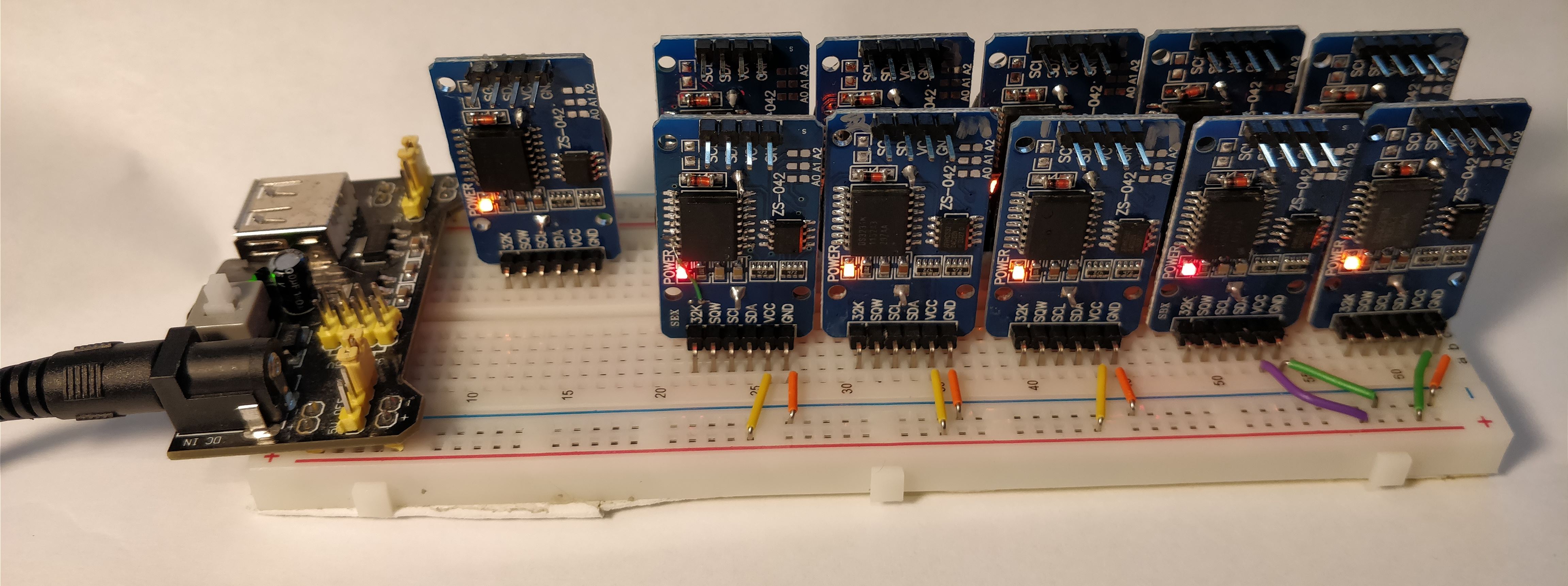
I wanted to test several DS3231 (M and non-M variants) boards for drift, so I mounted eleven of them (including one known-genuine DS3231M, the leftmost one on the front row, with a green bodge wire) to a breadboard, connected a regulated power supply (AMS1117) at 3.3V to both power rails, and made sure they all worked.
Eleven DS3231 (including 3 M variants) on a breadboard for testing.
Yup, they all work. The boards have either orange or red LEDs, so they emit a pleasing glow at night that prevents me from crashing into things in my office at home.
Why use 3.3V? One, it makes interfacing with the 3.3V I2C pins on a Raspberry Pi easy since I don’t need a level-shifter, and two, it minimizes drift in the event that I need to disconnect the power and have the clocks run on their coin cell backups. The CR2032 batteries have a nominal voltage of 3.0V, but all currently measure 3.3V (they’re brand-new, Energizer-brand cells from Digi-Key). The DS3231 datasheet says the drift can change by up to 1ppm/volt, so I want to minimize the voltage difference between the normal power supply and the coin cells.
To ease the comparison of drift, I want to ensure all the clocks start counting at the same moment. I could set them all one at a time, but this is complicated because (a) I don’t have an I2C multiplexer chip, and (b) setting them sequentially means they’re not all set at the same moment. It probably wouldn’t matter much in the long run, but it would make me happy to set them at the same time.
The DS3231 modules all have the I2C address of 0x68, and it cannot be changed. Normally, you cannot have multiple chips with the same address on the same I2C bus, as they’ll talk all over each other and the resulting signals will be garbage.
Fortunately, we don’t need the DS3231s to talk; they need only listen to the master and make the appropriate ACK/NAK signals as needed. They should all send the same ACK/NAK signals at the same time so, in theory, there shouldn’t be a problem.
Next, we need to worry about bus current. Each module has a 4.7k ohm pull-up resistor for the I2C bus. With eleven modules, that means the effective pull-up resistance is ~430 ohms. At 3.3V working voltage, a device would need to sink nearly 8mA to correctly signal a logic low. The Raspberry Pi I have can sink 16mA per GPIO pin, so that’s fine. The DS3231 datasheet says the IOL is 3mA, though I spoke with an engineer at Maxim Semiconductor and they said the absolute maximum current the process used on the chips is 10mA. 8mA is close to that limit, but the current would hopefully be spread across many devices and would only be for a few microseconds in total, so it should be fine.
I was satisfied I wasn’t going to blow anything up (and if I did, replacements are cheap), so I connected all eleven modules in parallel to the same I2C bus and commanded them to set their date and time to an arbitrary date in the past. If this was successful, I could send a command to read the time and, if all the modules had the same time, it would come through without an error. If things didn’t work, garbage would come in and I’d have to check them individually for the correct time. One read to all of the devices simultaneously, and I had valid data for that arbitrary time and date. Excellent. It worked!
Using the Raspberry Pi synchronized to a local NTP server (another Raspberry Pi running NTP with a GPS reference clock) within less than a millisecond, I send the command to set the date and time on all the modules to the current time on Friday 8 Sep 11:18:16 UTC 2017 (unix time: 1504869496). Reading the date and time from all the modules confirms they all have the correct date and time with no errors.
Now I’ll let them run for a while to see how they drift. A few have hand-tuned aging registers, so they should hopefully drift less than the others, while others use the default aging register of 0.
As should be clear from one of my earlier posts, I’m really interested in clocks and precision timekeeping. In particular, I rather like the Dallas Semiconductor DS3231 series of temperature compensated RTC/TCXO (real-time clock/temperature compensated crystal oscillator) modules.
Recently, I had ordered several DS3231 boards from my regular eBay vendor in Shenzhen for some testing, only to find two oddities: first, the factory had evidently gotten an incorrect chip with the same sized 0.300″ SOIC package as the DS3231. This chip was the wholly-incompatible DS1315. It happens, particularly at this price point and via gray market suppliers. No worries, I contacted the seller and they sent me a replacement board.
Update 2020-09-24: At the time this post was originally made, most of the Chinese sellers on eBay were selling real (but not guaranteed by Maxim) DS3231 chips that generally kept good time. At some point they started selling DS3231M chips without updating their listings (which described the item as being the more-accurate -SN variant). Today, it appears that whatever stocks of real DS3231 chips have been depleted and many people have contacted me to say they’ve ordered the common “DS3231 and EEPROM” items from eBay, AliExpress, Amazon, etc. and the chips are wildly inaccurate even though they’re marked as DS3231. Buyer beware. It’s probably a good idea to buy chips for serious purposes from legitimate distributors.
Dallas Semiconductor, now owned by Maxim Integrated, is well known for making some excellent real-time clocks (RTCs). Take, for example, the DS1307: it’s simple, works with essentially any cheap 32,768 Hz watch crystal, is easily accessible over I2C, and is extremely power efficient (500nA current when running the oscillator on battery power).
As great as it is, the DS1307 has a major drawback: it relies on an external crystal and lacks any sort of temperature compensation. Thus, any change in temperature will cause the clock to drift. A 20ppm error in the frequency of the crystal adds up to about a minute of error per month. Not so great.
Fortunately, Maxim also offers the DS3231, which is advertised as an “Extremely Accurate I2C-Integrated RTC/TCXO/Crystal”. This chip has the 32kHz crystal integrated into the package itself and uses a built-in temperature sensor to periodically measure the temperature of the crystal and, by switching different internal capacitors in and out of the crystal circuit, can precisely adjust its frequency so it remains constant. It’s specified to keep time within 2ppm from 0°C to +40°C, and 3.5ppm from -40°C to +85°C, which means the clock would only drift 63 and 110 seconds per year, respectively. Very cool.
I have a bunch of eBay-sourced DC-DC converters that I use for a bunch of purposes around the house. Most are ordinary “LM2596” (in scare quotes, as most seem to be clones: they’re marked as LM2596 and generally work well, but have different switching frequencies. Supposedly this is an issue with such things.) buck converters configured as adjustable, constant voltage power supplies where the output voltage is set by a multi-turn potentiometer. Very handy.
Others can be used in either constant voltage mode or constant current mode. For the latter, a serpentine strip of PCB trace acts as a low-value sense resistor. An LM358 dual op-amp integrates the difference between the voltage across the trace and a voltage set by a potentiometer, with the output connected to the regulator’s feedback pin via an LED so you can tell when the regulator is in constant current mode. Another potentiometer sets when the “charging” LED lights up; this is purely cosmetic, and the LED turns off when the current through the regulator drops below the setpoint set by the potentiometer.