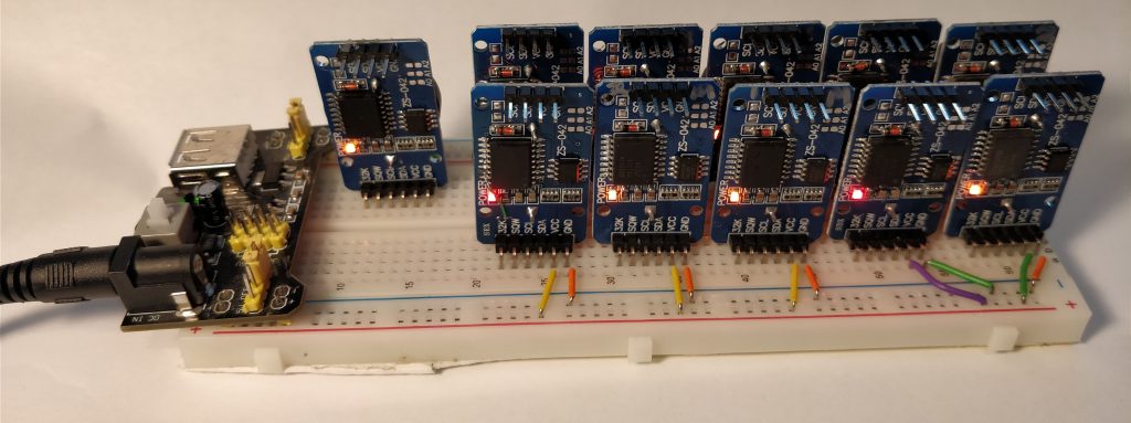
I wanted to test several DS3231 (M and non-M variants) boards for drift, so I mounted eleven of them (including one known-genuine DS3231M, the leftmost one on the front row, with a green bodge wire) to a breadboard, connected a regulated power supply (AMS1117) at 3.3V to both power rails, and made sure they all worked.

Yup, they all work. The boards have either orange or red LEDs, so they emit a pleasing glow at night that prevents me from crashing into things in my office at home.
Why use 3.3V? One, it makes interfacing with the 3.3V I2C pins on a Raspberry Pi easy since I don’t need a level-shifter, and two, it minimizes drift in the event that I need to disconnect the power and have the clocks run on their coin cell backups. The CR2032 batteries have a nominal voltage of 3.0V, but all currently measure 3.3V (they’re brand-new, Energizer-brand cells from Digi-Key). The DS3231 datasheet says the drift can change by up to 1ppm/volt, so I want to minimize the voltage difference between the normal power supply and the coin cells.
To ease the comparison of drift, I want to ensure all the clocks start counting at the same moment. I could set them all one at a time, but this is complicated because (a) I don’t have an I2C multiplexer chip, and (b) setting them sequentially means they’re not all set at the same moment. It probably wouldn’t matter much in the long run, but it would make me happy to set them at the same time.
The DS3231 modules all have the I2C address of 0x68, and it cannot be changed. Normally, you cannot have multiple chips with the same address on the same I2C bus, as they’ll talk all over each other and the resulting signals will be garbage.
Fortunately, we don’t need the DS3231s to talk; they need only listen to the master and make the appropriate ACK/NAK signals as needed. They should all send the same ACK/NAK signals at the same time so, in theory, there shouldn’t be a problem.
Next, we need to worry about bus current. Each module has a 4.7k ohm pull-up resistor for the I2C bus. With eleven modules, that means the effective pull-up resistance is ~430 ohms. At 3.3V working voltage, a device would need to sink nearly 8mA to correctly signal a logic low. The Raspberry Pi I have can sink 16mA per GPIO pin, so that’s fine. The DS3231 datasheet says the IOL is 3mA, though I spoke with an engineer at Maxim Semiconductor and they said the absolute maximum current the process used on the chips is 10mA. 8mA is close to that limit, but the current would hopefully be spread across many devices and would only be for a few microseconds in total, so it should be fine.
I was satisfied I wasn’t going to blow anything up (and if I did, replacements are cheap), so I connected all eleven modules in parallel to the same I2C bus and commanded them to set their date and time to an arbitrary date in the past. If this was successful, I could send a command to read the time and, if all the modules had the same time, it would come through without an error. If things didn’t work, garbage would come in and I’d have to check them individually for the correct time. One read to all of the devices simultaneously, and I had valid data for that arbitrary time and date. Excellent. It worked!
Using the Raspberry Pi synchronized to a local NTP server (another Raspberry Pi running NTP with a GPS reference clock) within less than a millisecond, I send the command to set the date and time on all the modules to the current time on Friday 8 Sep 11:18:16 UTC 2017 (unix time: 1504869496). Reading the date and time from all the modules confirms they all have the correct date and time with no errors.
Now I’ll let them run for a while to see how they drift. A few have hand-tuned aging registers, so they should hopefully drift less than the others, while others use the default aging register of 0.