Update 2020-09-24: At the time this post was originally made, most of the Chinese sellers on eBay were selling real (but not guaranteed by Maxim) DS3231 chips that generally kept good time. At some point they started selling DS3231M chips without updating their listings (which described the item as being the more-accurate -SN variant). Today, it appears that whatever stocks of real DS3231 chips have been depleted and many people have contacted me to say they’ve ordered the common “DS3231 and EEPROM” items from eBay, AliExpress, Amazon, etc. and the chips are wildly inaccurate even though they’re marked as DS3231. Buyer beware. It’s probably a good idea to buy chips for serious purposes from legitimate distributors.
Dallas Semiconductor, now owned by Maxim Integrated, is well known for making some excellent real-time clocks (RTCs). Take, for example, the DS1307: it’s simple, works with essentially any cheap 32,768 Hz watch crystal, is easily accessible over I2C, and is extremely power efficient (500nA current when running the oscillator on battery power).
As great as it is, the DS1307 has a major drawback: it relies on an external crystal and lacks any sort of temperature compensation. Thus, any change in temperature will cause the clock to drift. A 20ppm error in the frequency of the crystal adds up to about a minute of error per month. Not so great.
Fortunately, Maxim also offers the DS3231, which is advertised as an “Extremely Accurate I2C-Integrated RTC/TCXO/Crystal”. This chip has the 32kHz crystal integrated into the package itself and uses a built-in temperature sensor to periodically measure the temperature of the crystal and, by switching different internal capacitors in and out of the crystal circuit, can precisely adjust its frequency so it remains constant. It’s specified to keep time within 2ppm from 0°C to +40°C, and 3.5ppm from -40°C to +85°C, which means the clock would only drift 63 and 110 seconds per year, respectively. Very cool.
The one (very minor) downside is that it draws about twice the current, a bit less than 1 μA, than the DS1307. Still, a common 220mAh CR2032 battery could power the chip for at least a decade with no problem. Such a circuit would be mostly limited by the CR2032’s self-discharge rate anyway.
In my case, I wanted to use such RTCs on several of my Raspberry Pis that are not regularly (read: almost never) connected to the internet, and so cannot always get their time from NTP servers.
Some clever person designed a very simple board that fits on the Raspberry Pi’s pin headers for power, ground, and I2C and has the DS3231 chip, pull-up resistors for the I2C bus, and a decoupling capacitor. It even has pads for a backup battery (not included, but adding a battery holder and coin cell is straightforward). Chinese vendors on eBay sell the board for about $1.50, with free shipping. Perfect.
Here’s the board I’m using on one of my Pis, along with the backup battery and holder I added.

Considering that the DS3231 is not a cheap chip, costing ~$3.80 USD per chip in minimum quantities of 1000 from Digi-Key, it’s a bit surprising that complete board only costs $1.50 per board. Like Edward Mallon, I wondered if these were counterfeit chips that were pin and function compatible, QC rejects, or somehow otherwise illegitimate chips.
For science, I ordered a few extra boards and tested them over the last year, where “tested” means “set the time on the chips with a Pi that was NTP synchronized to a GPS timing receiver, disconnected them from the Pi, and left them on the shelf running on battery power for a year”. The chips would be in direct sunlight in the mornings, and the temperature in the room would range between about 15°C and 30°C throughout the year. Not extreme, but not precisely regulated either. I did not adjust the “aging register” in the chip to trim the oscillator before this test, and the register was set to its default value of “0”. After a year, the chip with the largest drift was only 16 seconds off, which is about 0.5 ppm. That’s well within spec, so I’m happy. If these chips were counterfeit, they were at least good counterfeits that worked as advertised.
However, I wanted to look closer so I sacrificed one of the chips for science. Thanks to my friend Jesse for reminding me that I can just snip off the legs of the chip rather than trying to de-solder it. That made things a lot easier.
Here’s the top of the package. It claims to be an SN model, which means it is specced for the full -40°C to +85°C temperature range. The date code says it was made in week 33 of 2011, as part of lot 917AC. The # mark means it’s RoHS compliant.
The laser markings seemed a bit dodgy and not like the normal high-quality laser markings I see on other Maxim chips. I contacted Maxim, explained the situation, and sent photos of the package and die (see below). After checking their records, they say the style of the markings, the date code, and lot number are all consistent with that particular lot made in 2011, which strongly suggests the chips are legitimate. They also reminded me that they do not warrant or guarantee any products purchased from unauthorized resellers. Good to know, and not unexpected.
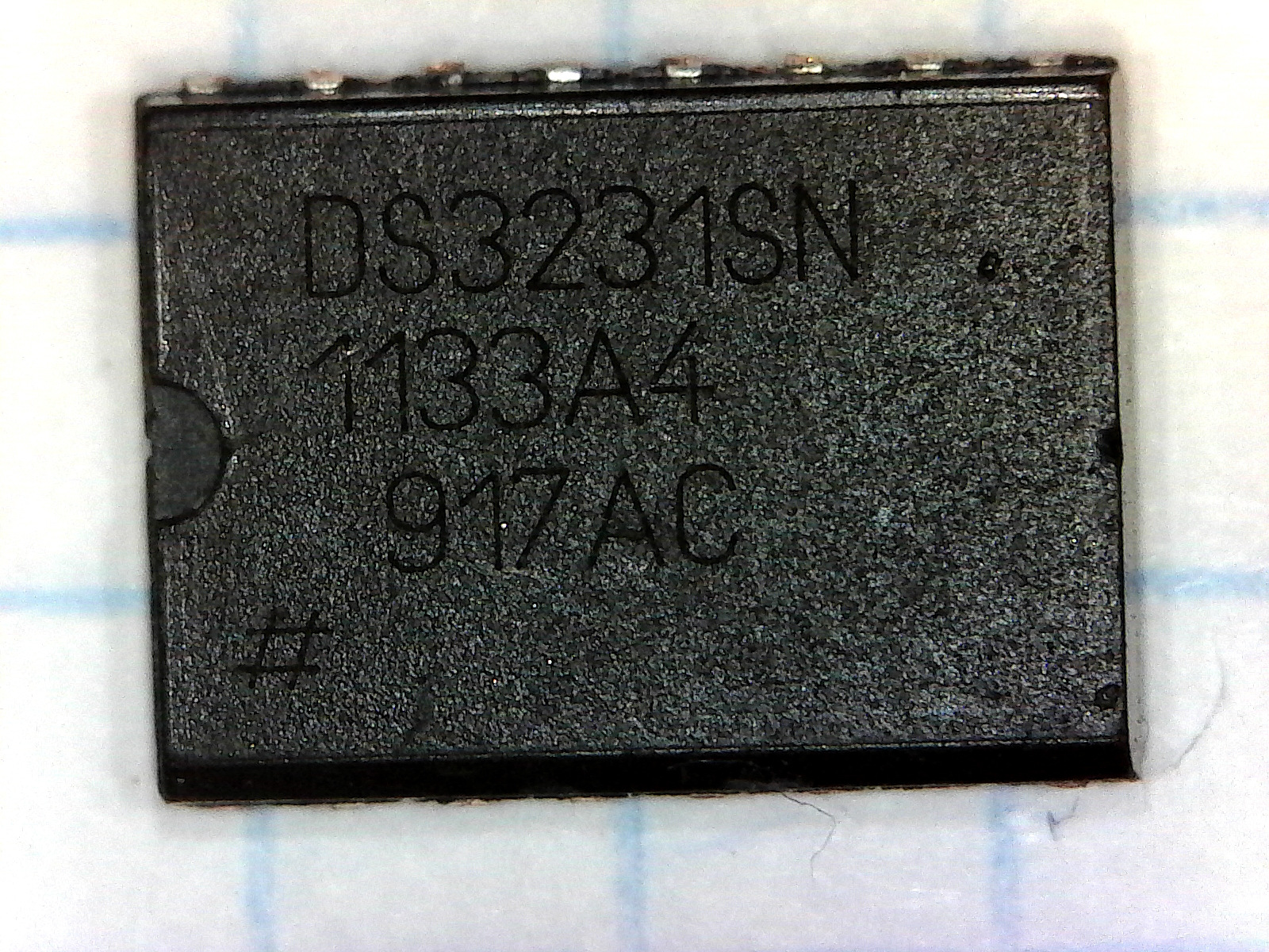
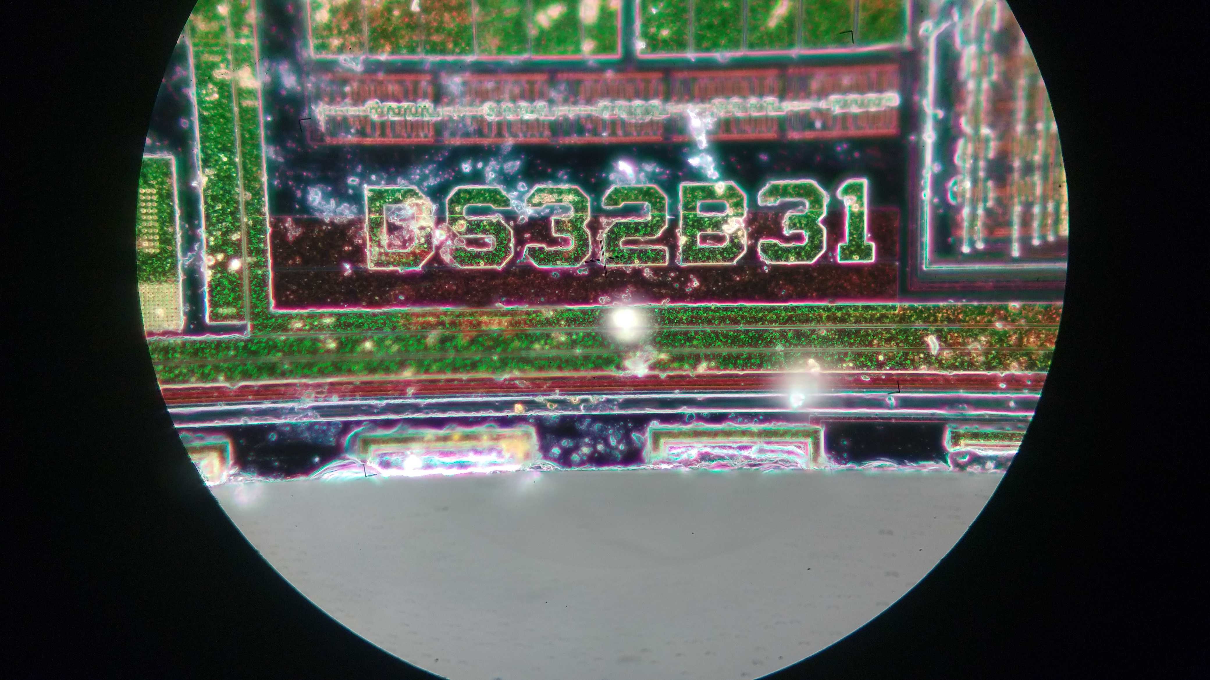
I zoomed in with my USB microscope to examine the markings in more detail. It’s a bit hard to see in this close-up, but you should be able to see the digits “31”. Compare these markings to those on the Maxim MAX3232 chip I investigated earlier and you can see why I was a bit skeptical as to their legitimacy at first. Obviously, Maxim must have different types of laser marking equipment on their different production lines.
I normally would digest the epoxy packaging of the chip in acid at work, butI was at home that day and didn’t have access to the chemicals and safety equipment I have in the lab at work, plus I didn’t want to dissolve the integrated crystal and its metal can. Instead, I embrittled the packaging by heating it in the flame of a common Bic lighter for several seconds and then quenching it in a glass of cool water. I repeated this process several times.
Next, I sanded down the back of the ship (assuming that the interesting parts of the die would face upwards, which they were — if they hadn’t been on the top, I’d sacrifice another chip and sand the top down) with fine sandpaper until I hit metal.
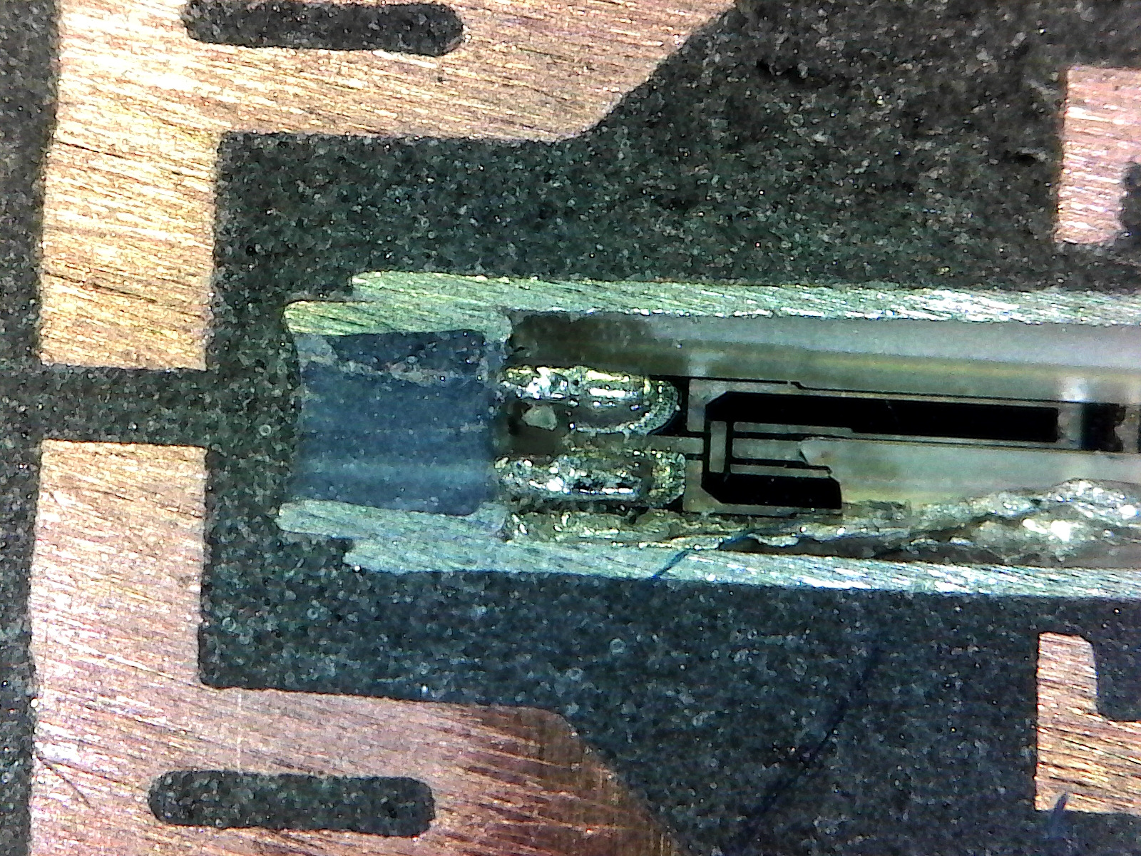
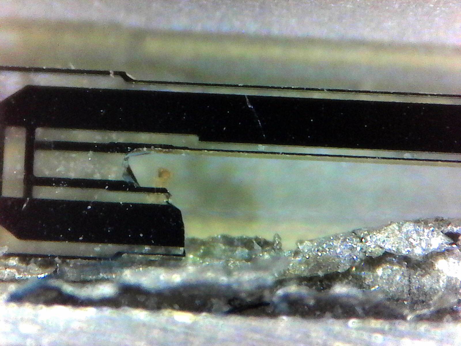
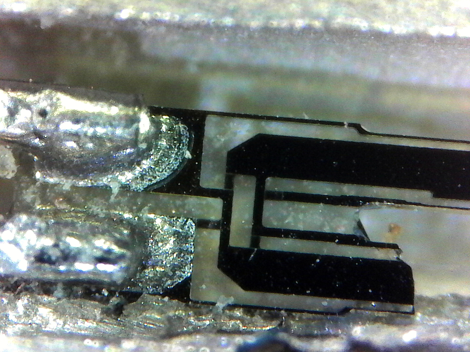
It turns out I was a bit too vigorous in my sanding, and accidentally sanded through the crystal’s metal housing and broke one of the forks of the tuning fork oscillating element. Oops.
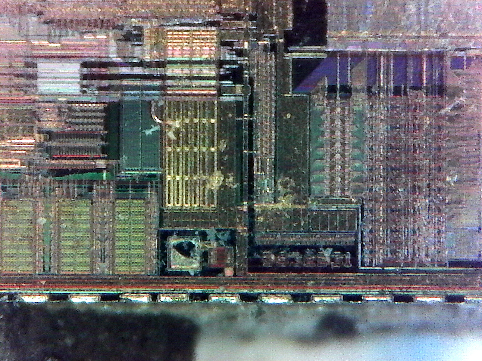
In the photos below, the notch on the chip is to the left, so pin 1 is to the top left. The main die is behind the large copper pad to the left. The fuzzy “hair” at the bottom are strands of the epoxy package that I didn’t clean up.


This was interesting, but even after Maxim said the packing and exterior markings looked legitimate, I was curious if the die itself was an actual Dallas/Maxim die or if it was a fake. Using tweezers and a fine, sharp knife I was able to crumble away more of the epoxy package and remove the die. Unfortunately, the bond wires were still embedded in the package and so broke off when I removed the die. I also slightly scratched part of the die and cracked off part of the top-right corner. Clearly, acid digestion is the way to go.
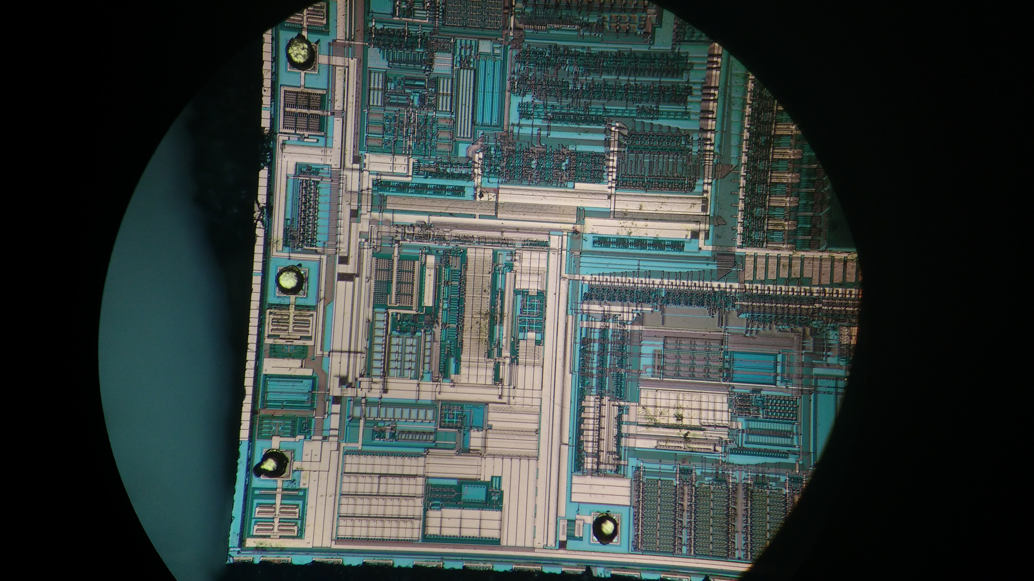
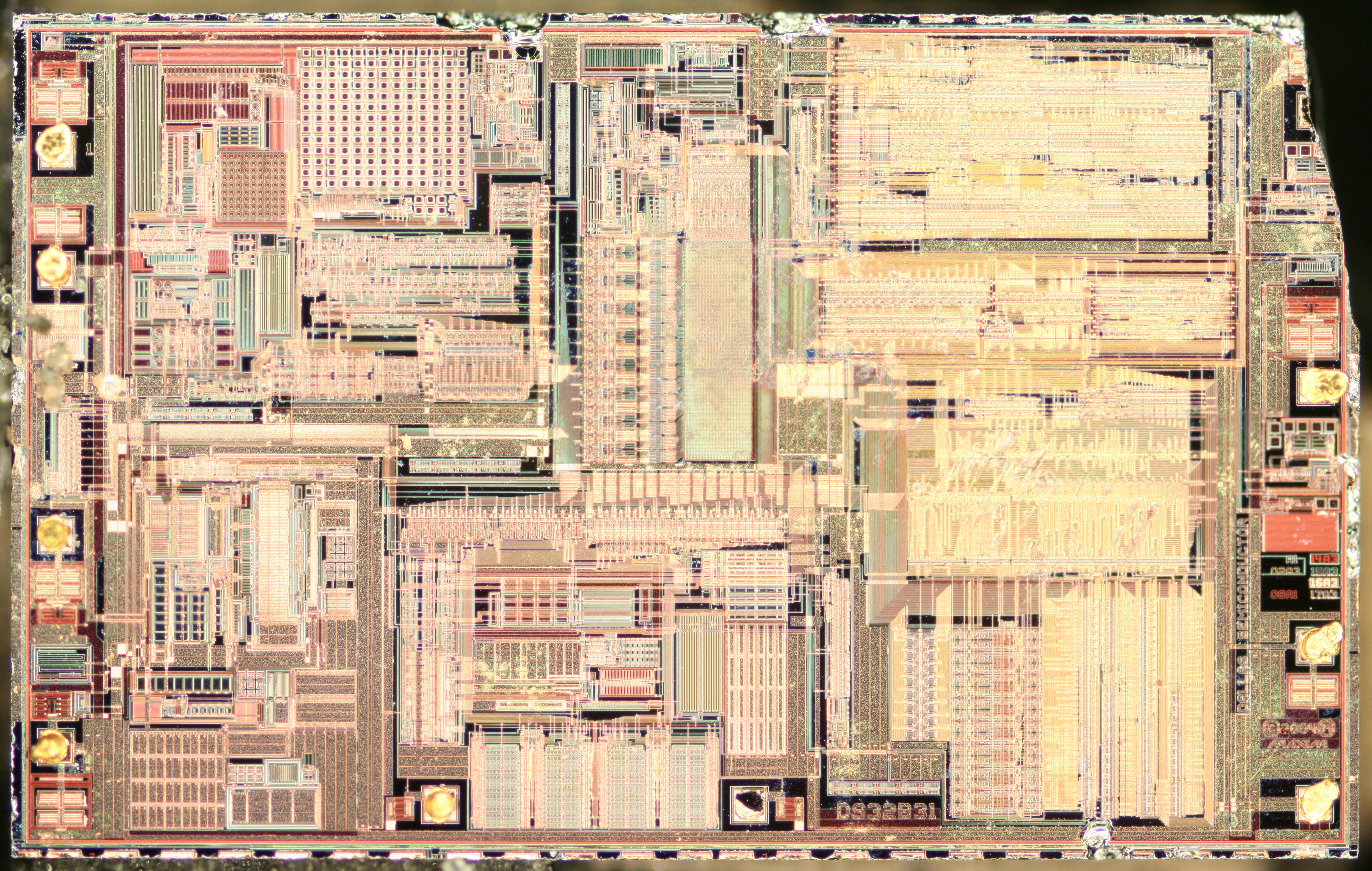
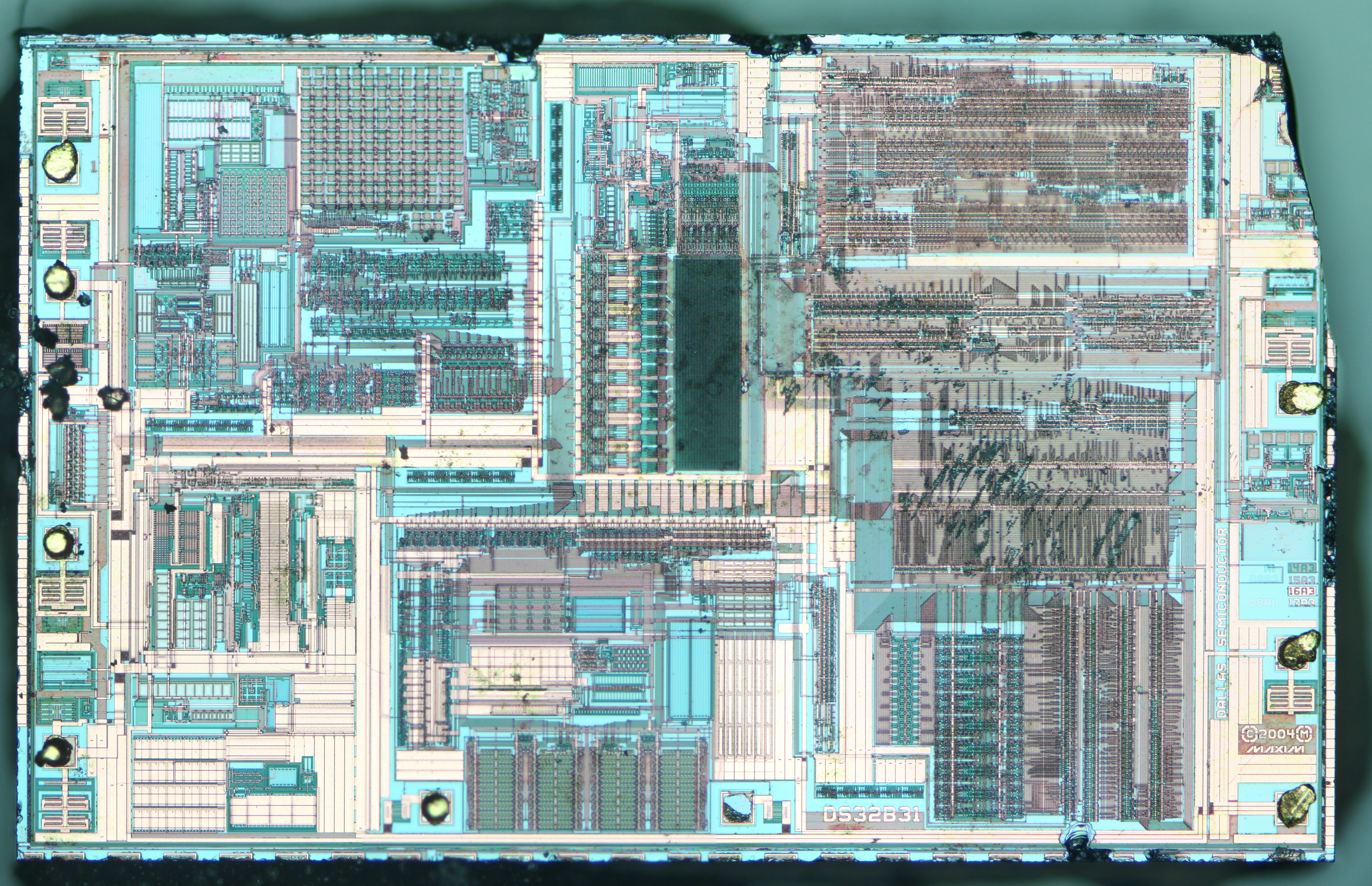
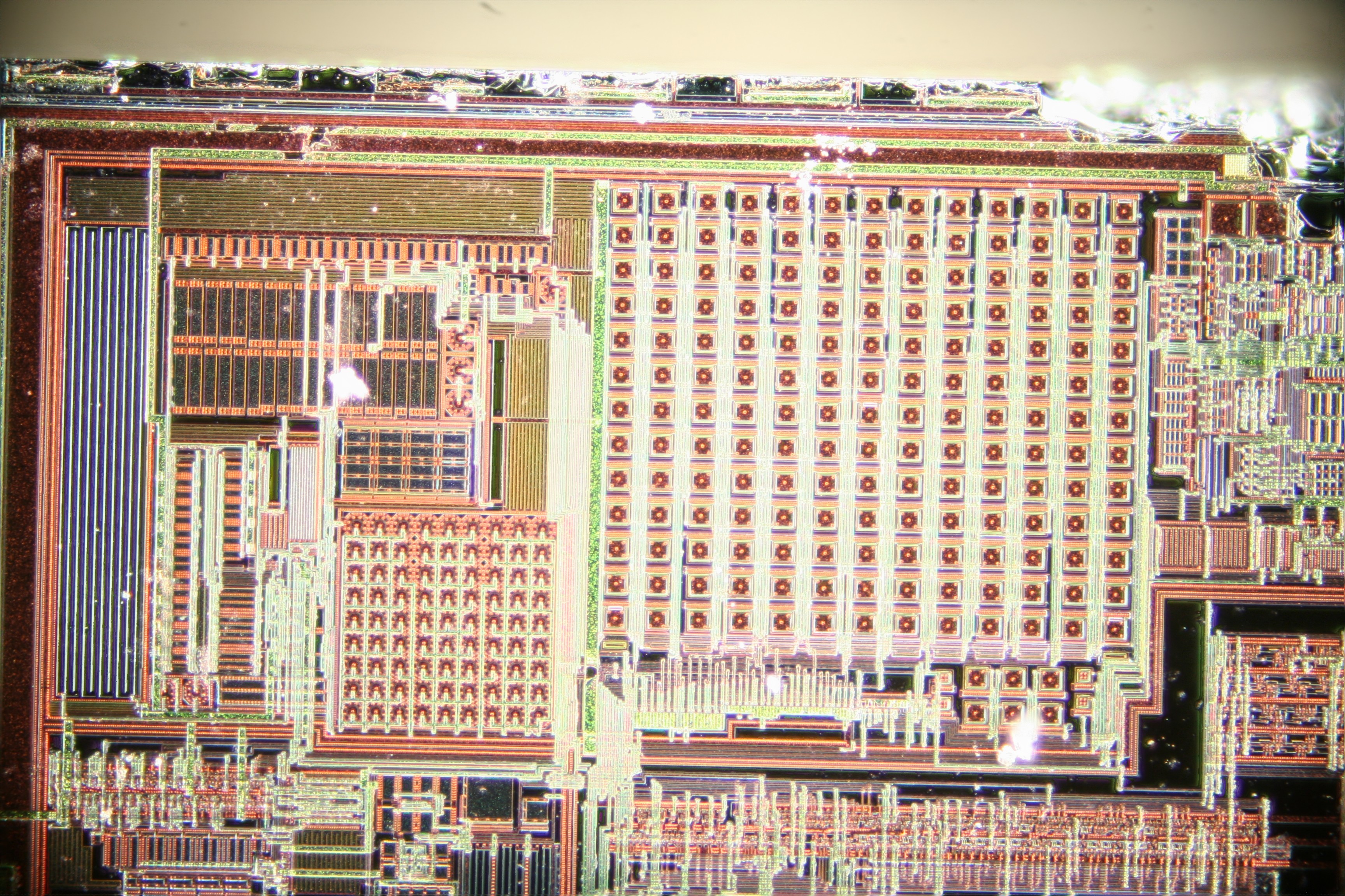
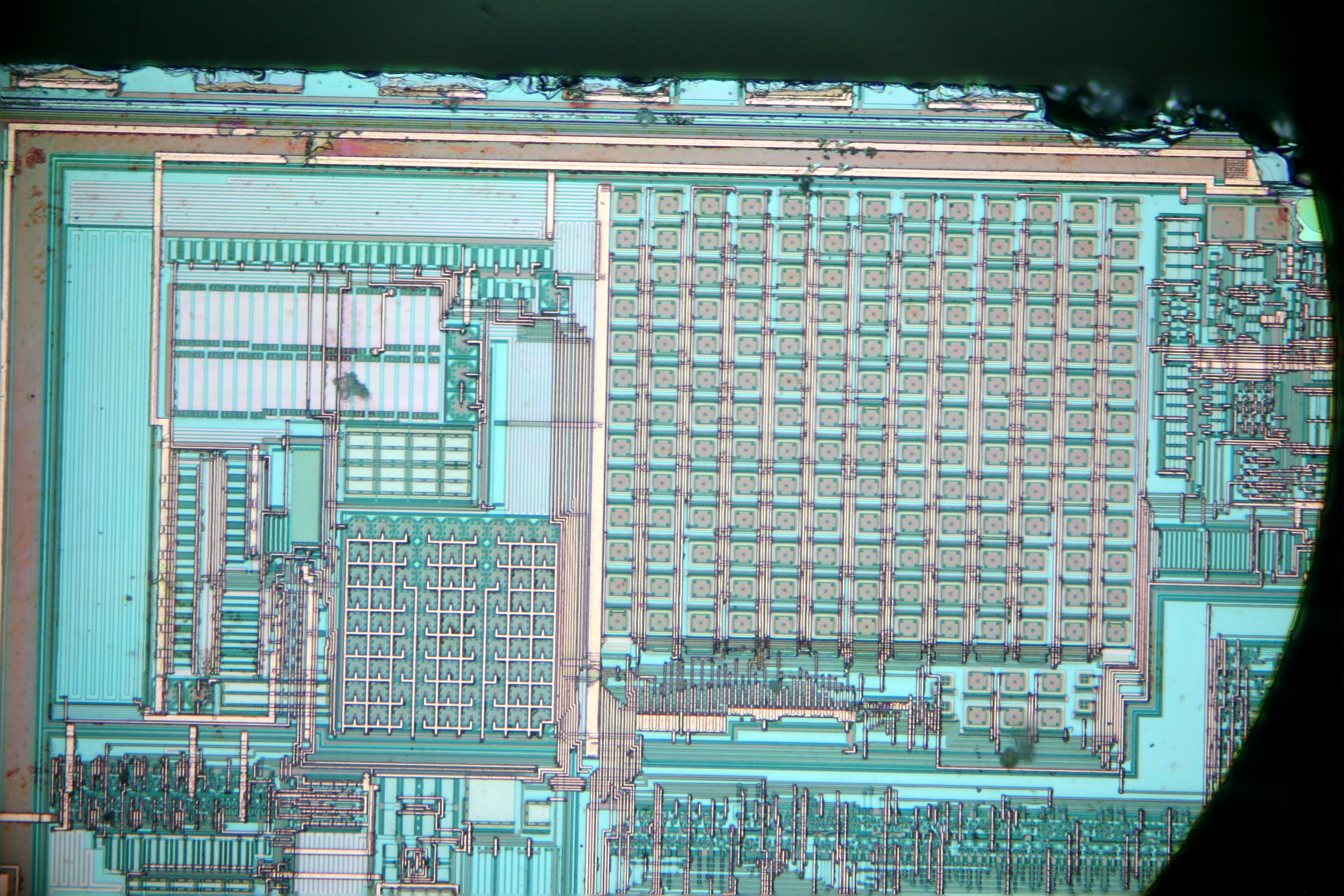
Here’s the first look at the die itself. I had washed it with isopropanol and both the chip and the microscope slide are a bit wet. The die measures ~3.6 x 2.3 mm, and the images below were taken with my USB microscope.
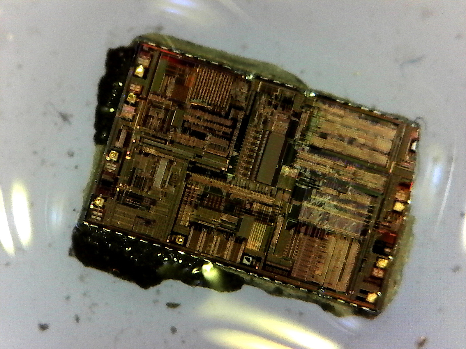
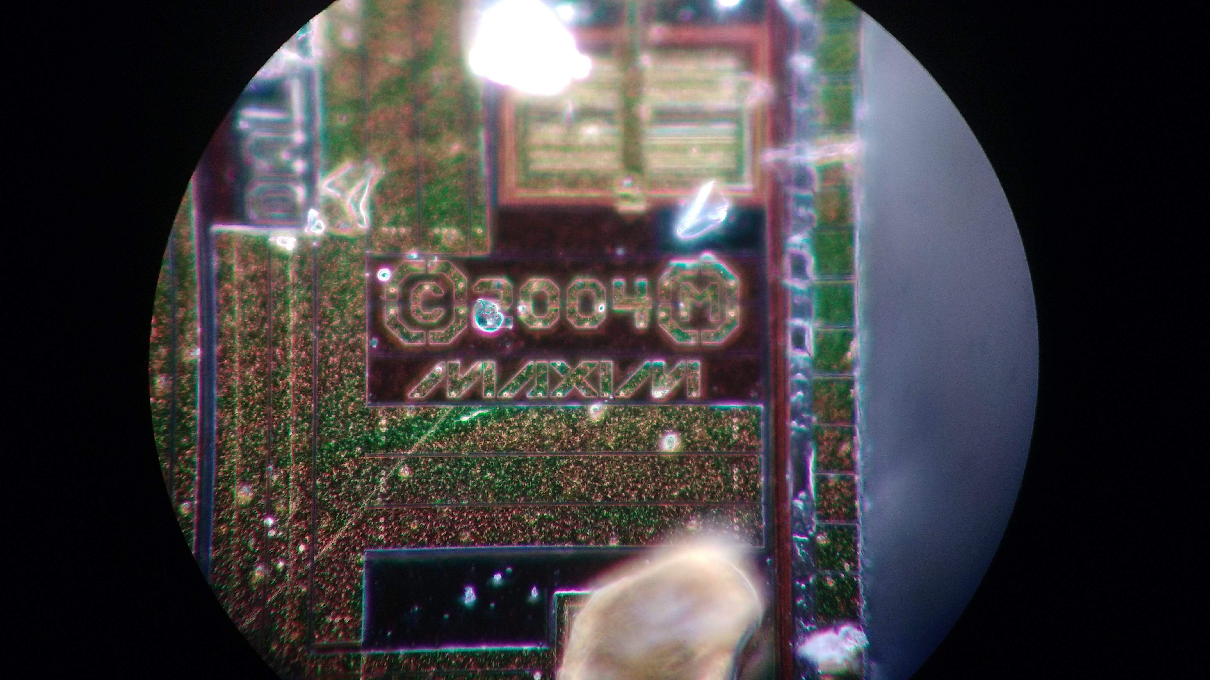
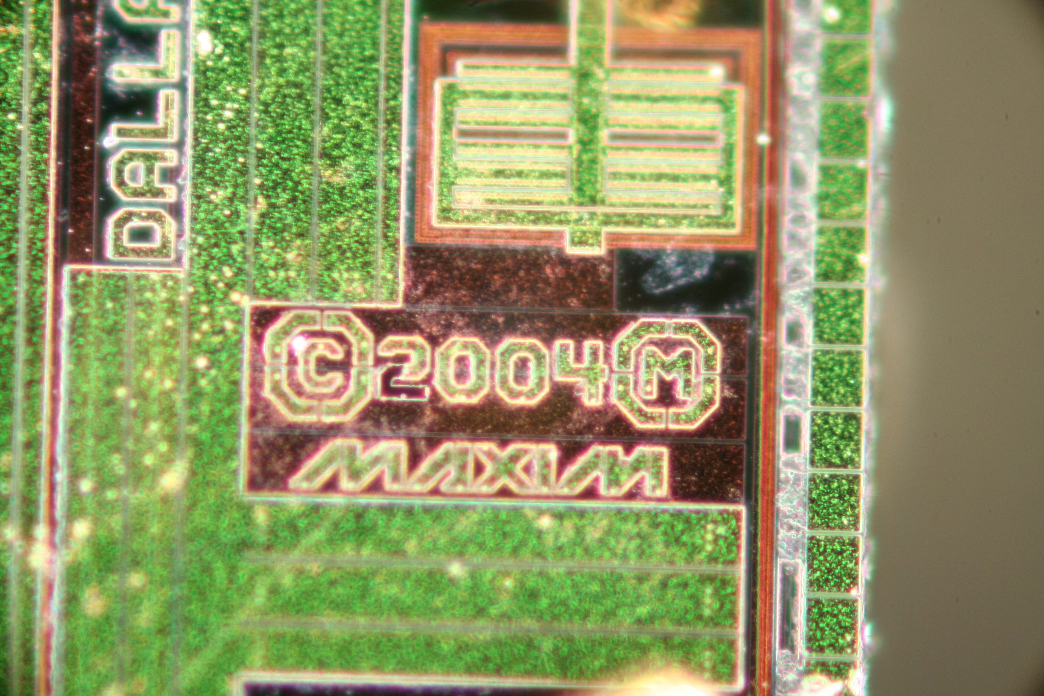
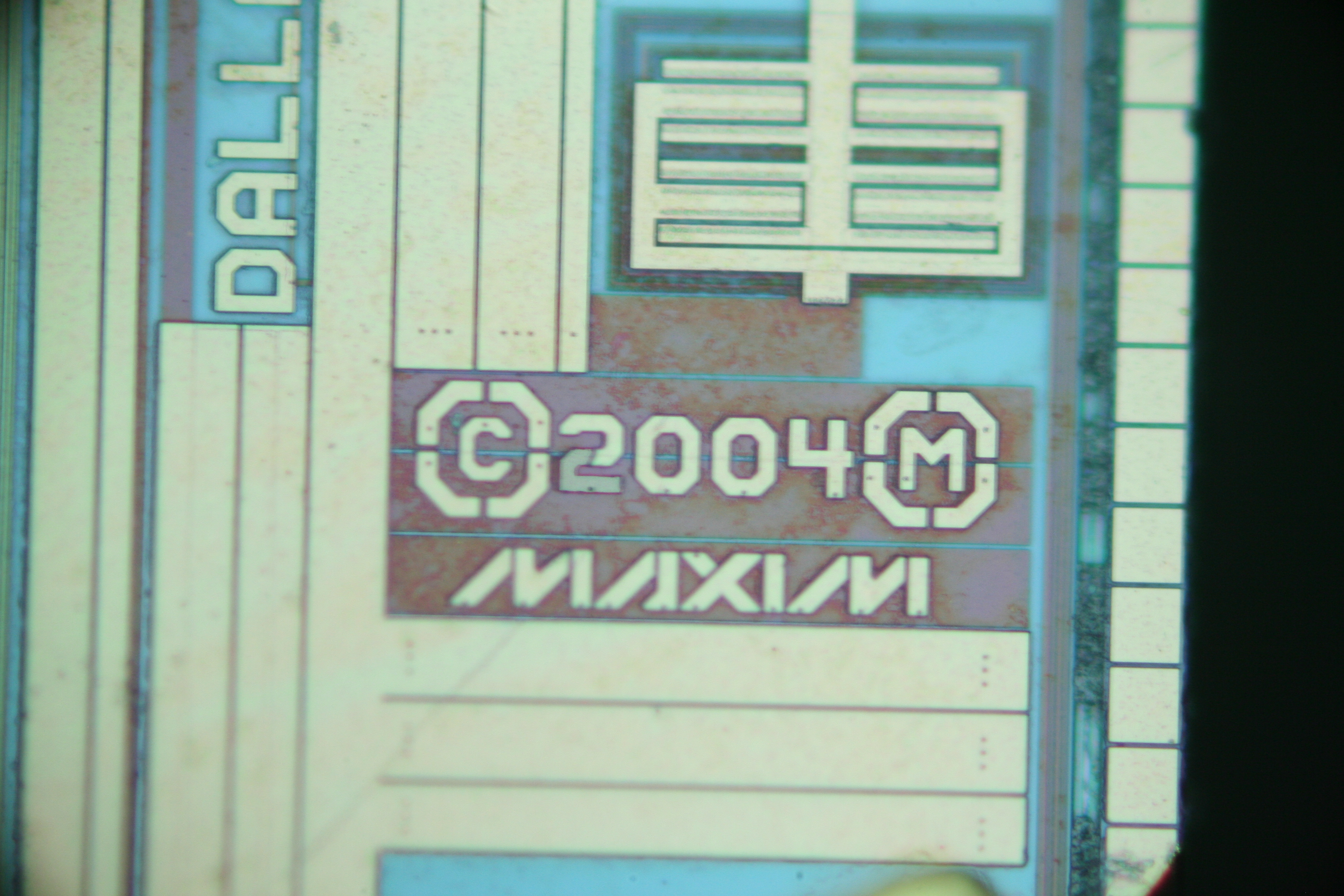
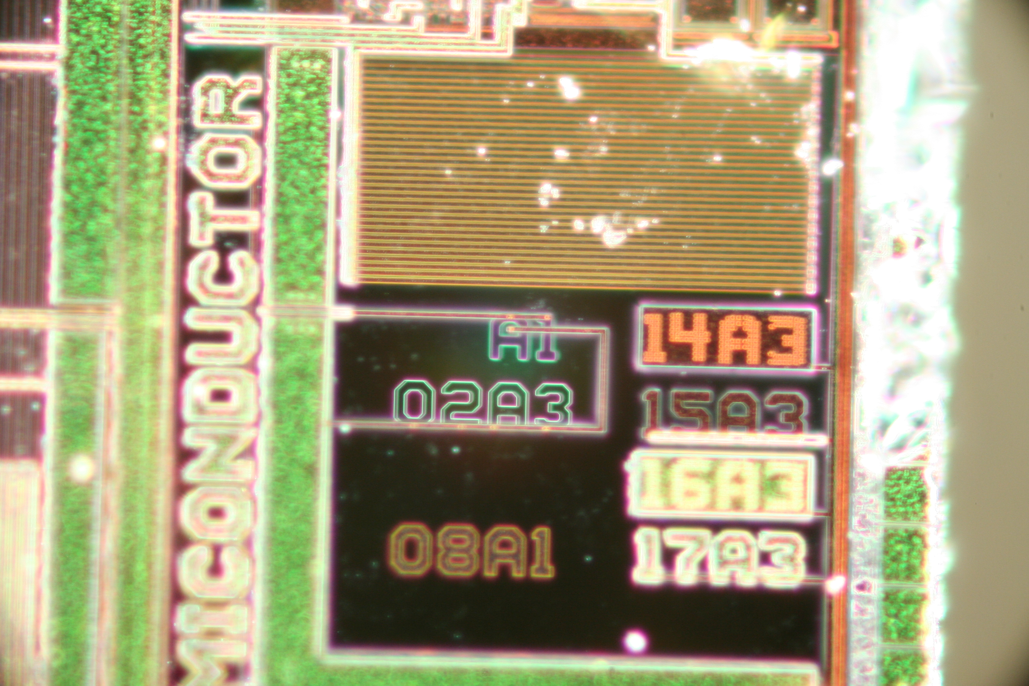
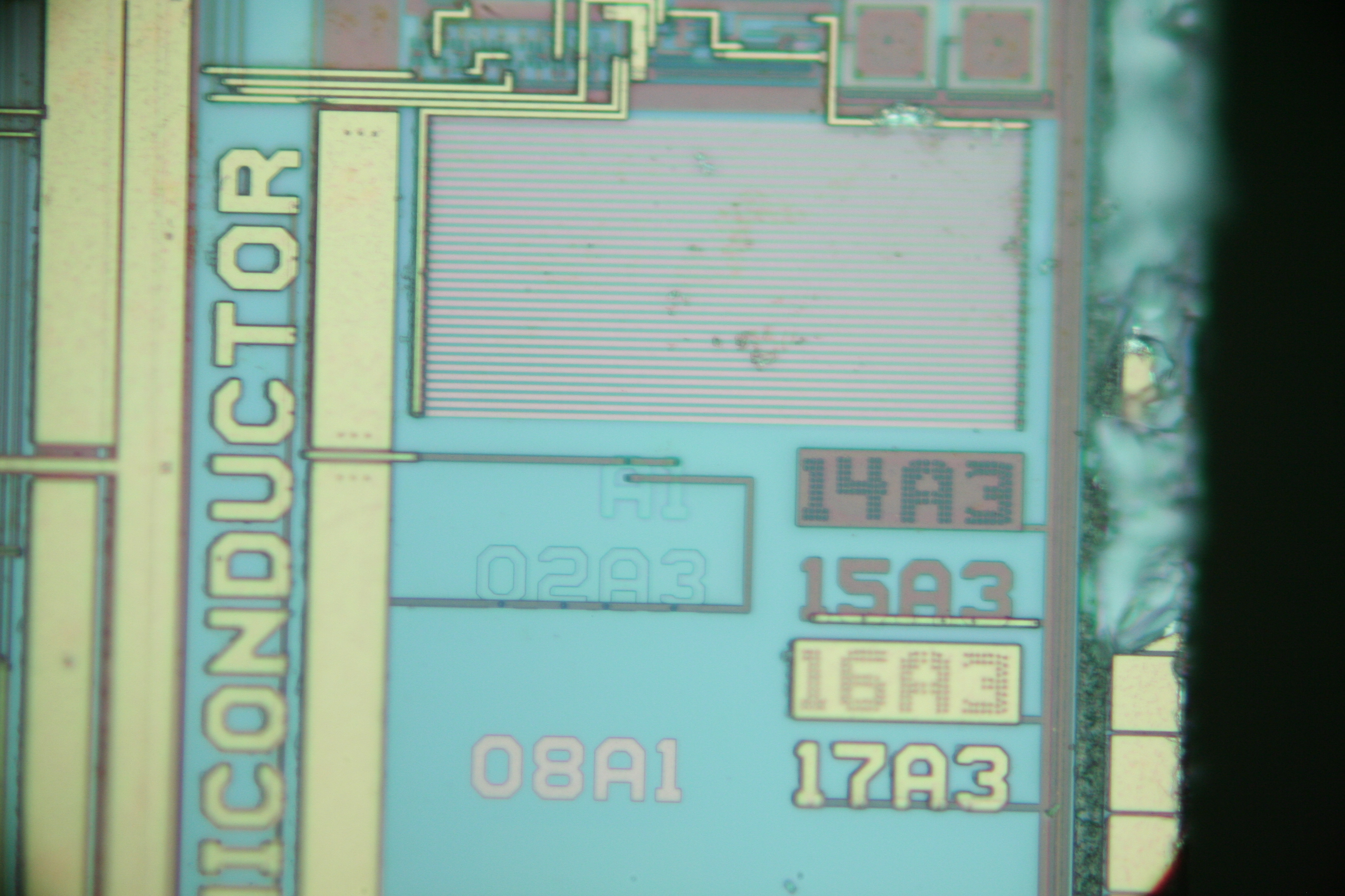
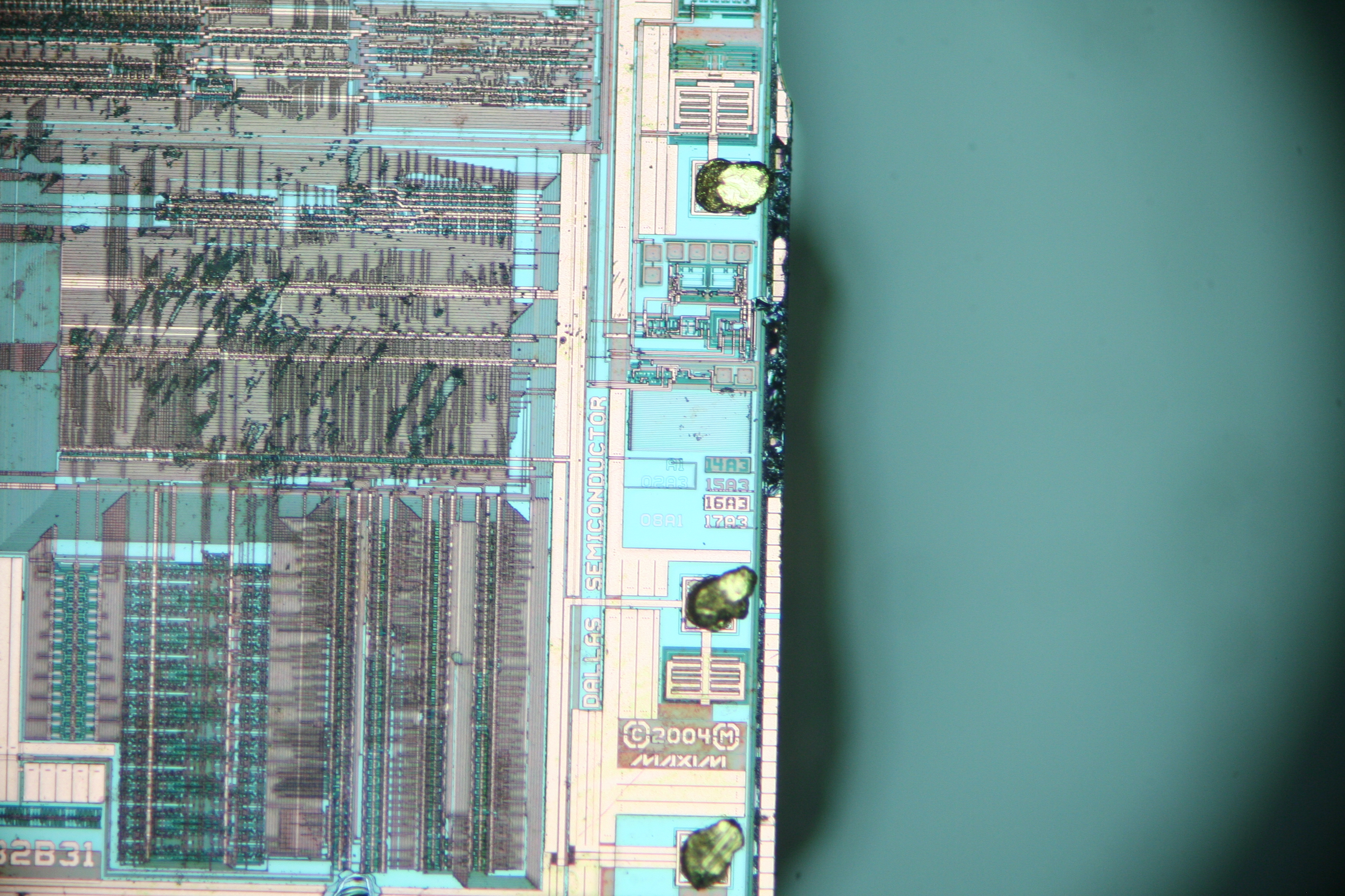
First, I wanted to check to see if the die was actually made by Maxim or if it was a fake. The die clearly says “DALLAS SEMICONDUCTOR”, as well as “©2004 (M) MAXIM”. Looks legit. That’s refreshing.
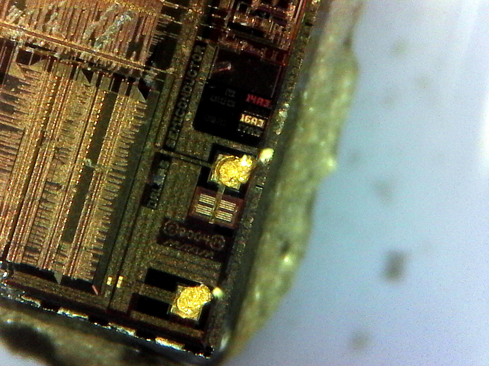
Here’s some more photos of the die.
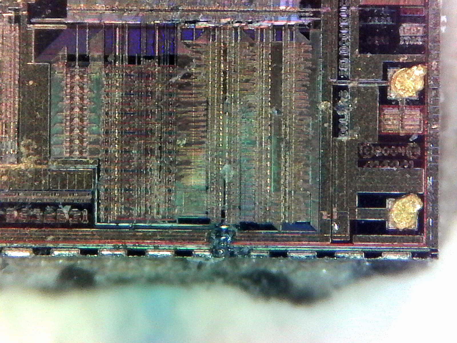
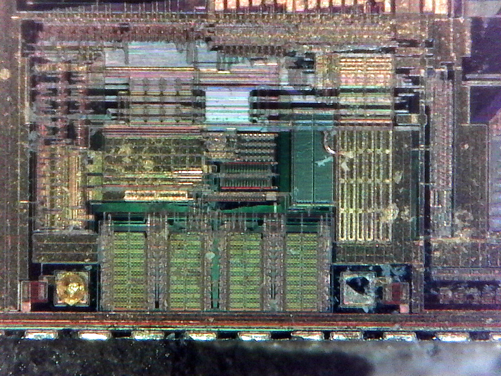

In addition to my cheap USB microscope at home, I was later able to take the die into the lab at work and use the (very expensive) Zeiss microscope to take more pictures. I was also able to clean it more thoroughly using the ultrasonic cleaner so the images came out considerably better.
Alas, compatibility issues between the camera mounted on the microscope and my computer prevented me from using the camera to get high-quality photos at this time. I’ve ordered an adapter so I can get better photos, but it will be several weeks. At that time I will either update this post or link to a new one. I plan on creating large composite images of the die at various levels of zoom, and with different optical filters. In the interim, here are a few photos I took using my smartphone aimed through the eyepiece of the lab microscope. They are nowhere near as clear or stunning in appearance as they are when viewed directly through the eyepiece or via the on-scope camera.
Addendum 2017-07-29: I’ve been able to get the camera on the microscope to cooperate and have gotten several high-quality photos. As the microscope has an extremely short depth of focus, particularly at high magnification, some images have been “focus stacked” by combining several images at different focus depths. Similarly, the large composite images are made from several individual images that may be focused slightly differently from each other. These processes may cause visual artifacts to be present.
In general, images with green and red colored layers use standard reflected microscopy with no filters, while images with blue and gold layers use reflected differential interference contrast (DIC).
That’s all the photos for now. I hope you found this as interesting as I did.
Great work.
Can you tell me where to get a good AND inexpensive USB microscope?
Thanks much.
Thank you.
I’ve been generally quite satisfied with this one from Plugable. It’s basically a webcam with a macro lens, but it does reasonably well if you have a solid stand.
Quick follow-up: keep in mind that I bought that microscope a few years ago and haven’t looked into the USB microscope since then. It’s quite possible that there’s much better ones available now.
My work’s Zeiss microscope is outstanding, but not inexpensive. I seem to recall it costing as much as a decent car. Probably outside of the typical home budget.
Maxim probably doesn’t package their own chips but outsources it. Dallas Semiconductor didn’t when I worked there. The wafers were sent off shore to be ground down, sliced and packaged, then sent back to DFW area for testing. Wafer test was right next to package test since we used the same test equipment and engineers.
Components are expensive for hobbyist, since most chips sell in lots of 10,000 and there’s overhead in shipping and handling singles.
Having an outside company do the packaging doesn’t surprise me at all.
That said, I’m not entirely clear on one of your statements: you say that the wafer test and package testing was right next to each other. To be clear, does this mean you did wafer testing prior to sending the wafers off for processing and packaging?
I’m curious, because people have asked me if the chips in these Chinese modules are likely to be “ghost shifts” or QC rejects, but if Dallas/Maxim does the testing prior to the wafers leaving their own controlled fab, it’d be hard for such things to take place.
And yes, I know that bulk sales get discounts on the cost per chip, but Digi-Key sells them for $4.51 in quantities of 1,000. Perhaps one could get a bigger discount at even larger volumes, but I have no way of knowing.
One other thing stood out to me: the date codes on the chips used on these Chinese modules typically range from 2008 to 2011. It seems a bit odd to think they’d keep chips lying around on shelves for 9 years only to sell them on cheap modules. Still, I don’t see any obvious evidence of having been de-soldered from some other installation and being re-used. Very strange. Any ideas?
Yes, wafers are tested prior to shipping. A “prober” puts the wafer on a chunk and moves it to a stationary probe card with test leads, “probes” that touch the bond pads of each die. A pass/fail/bin map is made for each wafer in the lot and bad die may be marked with ink. The probes are hooked to a tester which test the die. The same type tester may be used on the finished package. Chucks can be heated or not and special baths may be used to calibrate oscillators or temperature sensors. Lasers can blow fuses for various purposes or serial numbers. More secure chips get extra layers of metal and oxide to obstruct reverse engineering.
Date codes may not be related to package date, but the lot date in the fab. (Wafers can sit for years before packaging…) But with the Chinese, who knows?
Interesting, thank you for the details. I didn’t know that wafers might sit around for a while until being packaged, but that makes sense. It sounds like it’d be hard for rejects to make it out into the wild in any reasonable quantity, so that lends credence to all these chips on the market being legit, though of “gray market” origins.
The main market for these chips are utility meters made in China. The price that a contract assembler pays in China is much less than a dollar, the actual prices are a highly guarded secret.. These parts are “grey” marketed out of a contract assembler into the hobbyist market. They’re new prime parts but could have reel ends, drops or misfeeds or just surplus to their needs.
Fascinating! Do you happen to have any links to more information about that? I know a few people in the time-nut community that would be interested in more details, as they’re skeptical of the sources for these chips.
Also, any insight as to why most of the chips are relatively old (e.g. 2008-2011 vintage) even on items purchased in 2017? I can’t imagine the manufacturer would keep a big warehouse of old chips lying around gathering dust until they decide to surplus them out, but I’m a physicist, not an electronics engineer.
One thing to keep in mind is that chips have an expiration date. If the lots are too old, they’ll be rejected for use on “real” product. What you may have is a batch of old Maxim parts that someone found mis-stocked in the warehouse, too old for current customers to use. They run out a batch of board for the grey and hobby markets, and don’t fret the fall out.
With age, the packages absorb water and the tinning on the leads begin to oxidize a/o crystallize. The results are exploding packages during reflow, and bad solder joints.
Interesting. The tinning on the leads looks fine, and the solder joints look properly wetted, so I don’t think I should worry too much about them. Am I correct in assuming that since the joints look good and the packages haven’t exploded, things are pretty good (in terms of hobby-type reliability, not for any sort of critical system)?
Excellent investigation, including some nice info on the photography and lighting. As a clock fan, I found the article particularly appealing, although 16 seconds in a year is not even close to the performance of the best mechanical clocks (1 second in 100 days is the current ‘standard’ to aim for). On the other hand; for a cheap chip, the results are impressive in terms of accuracy v. cost.
Thank you!
What sort of mechanical clocks are you referring to? I wasn’t aware that precision mechanical clocks were even still being made these days, and that even the more demanding roles (e.g. marine navigation) had been replaced with electronic clocks. I’d love to know more.
Also, keep in mind that I had not adjusted the aging register in the chip, and it is operating within the published specifications (which is pretty good for a quartz crystal) of +/- 2ppm. I’m currently setting up a test rig for measuring several modules at once but, in the interim, have used my oscilloscope, stopwatch, and GPS disciplined oscillator as a reference to measure the time needed for the DS3231 to drift a certain number of cycles over time. Right now, the five I have tested are all around 0.5ppm, which is in line with the one I left on the shelf for over a year for testing — that’s about a factor of 5 worse than your 1-second-in-100-days mechanical clocks.
However, by tuning the aging register in the DS3231 I can increase the stability quite a bit more: I’ve had a few running at <10ppb for at least several hours (then the baby woke up and I had to feed him) with a bit of tuning and luck. Due to that adjusting the capacitance on the crystal, things get a bit nonlinear at temperature extremes according to the datasheet, but at the temperatures encountered in this room it's not really an issue.
Honestly, I was a bit surprised that such a simple, cheap, and low-power device can regulate the frequency of the crystal as well as it can.
Mechanical cloks are full of surprises. For me, the first noteworthy clock capable of precise timekeeping was probably the Littlemore clock: http://www.hsn161.com/HSN/hsn_article.php
and some interesting observations at: http://www.cleyet.org/Pendula,%20Horological%20and%20Otherwise/The%20Littlemore%20clock%202.pdf
where Littlemore was said to be disappointed his clock would not detect the changing tides!
The observatory clocks by Fedchenko and by Reiffler and by Short were all impressively accurate. Woodward’s clock, and the subsequent remakes, especially DW5 by David Walters (a real beauty), could be made by mere mortals, and exceed an accuracy of 1 second in 100 days.
I recently visited the Royal Observatory in Greenwich, Uk, where the Burgess ‘B’ has been on test and has been declared the most accurate mechanical clock ever made, with an error of less than 1 second in 100 days. There’s a useful collection of information about that clock, here: http://leapsecond.com/pend/clockb/
One interesting difference between these pendulum clocks and the quartz mechanisms is that the pendulum reacts to variations in temperature and atmospheric pressure (when the pendulum is not enclosed in a vacuum), and, more intriguingly, gravity, and the tides. The quartz movement is not influenced by all of those factors, as far as I know. Temperature; yes – but gravity and the tides: – I don’t think those cause a measurable deviation in rate.
It’s an interesting field. Oh yes; let’s not forget magnetic fields.
The aging register is useful, and is calibrated in the more precise QMs, but I wonder whether it can be tweaked more than once, as time goes on and the crystal ages further.
Thanks! I know what I’ll be reading over the next day or two once the kids are asleep.
In regards to the aging register in the DS3231, it absolutely is re-tweakable. It’s just a one-byte value in RAM, and one can read/write it over I2C just like any of the other registers on the chip. The new value is used for the next automatic temperature conversion (either automatically triggered on schedule, or manually triggered by setting the appropriate bit). The only caveat is that a non-zero aging value causes non-linearity in the frequency corrections at the temperature extremes (that is, it acts more like a regular crystal rather than a TCXO). If the chip is, as many are, in a reasonably stable environment it’s not really a problem.
Based on some quick tests at home, if the temperature in the room stays reasonably stable (e.g. standard residential temperature variations) and aging over one year is negligible, the chip will remain within +/- 1 second/year once I tune the aging register for maximum stability. That’s pretty good.
One other neat thing: the DS3231’s register layout is a superset of the DS1307. This makes it easy to do a drop-in replacement of the DS1307 with the DS3231 without having to change any other aspects of a system (so long as one is only concerned about the time itself, and not things like the temperature sensor and the like).
Fascinating stuff! Can you describe your procedure for tuning the aging register? Are you just trimming it until you find the best accuracy fit compared to a reference clock over some time period at ambient temp? Thanks!
In short, yes. I’m using a method similar to the analog method from here to do the tuning, with a few minor variations:
– The reference signal is a 1pps signal from my Trimble Thunderbolt GPSDO, which has an accuracy of +/- 20ns or so. This is fed into my oscilloscope as the trigger signal.
– The 32.768 kHz signal from the DS3231 is connected to a Schmitt trigger to clean up the rising edge (the module I have has a 4.7 kOhm pull-up, so the rising edge is a bit slow), the output of which goes into one of the channels on the oscilloscope.
I set the oscilloscope to 1-2 microseconds per division, then watch the pulses drift left or right over time. I start a timer when one of the pulses reaches one of the marks on the graticule and time how long it takes for the pulses to drift such that a different pulse reaches the graticule. Usually, it takes a minute or two with the un-trimmed oscillator, which corresponds to 0.25-0.50 ppm.
The DS3231 is connected to an Arduino running a sketch I write to read and write the aging register. Input and output goes over serial to the computer. This is all at room temperature.
I’ve been meaning to test things at different temperatures (e.g. in the freezer), but life has been a bit busy as of late, so I haven’t had time.
Check out a book “The Perfectionists” – by Simon Winchester.
It is the history of how measurement and manufacturing has improved over time. Each chapter is an order of magnitude.
One chapter deals with timekeeping, from pendulum clocks to pocket and wrist watches. The first pendulum clock brought to America did not work right because of the difference in gravity vs England. Also an account of Seiko how they went from mechanical to electronic, and (partially) back to mechanical.
There is also a chapter on the creation, then modification, of the meter and kilogram.
Overall, a fascinating book for nerds.
These are some pretty cool looking pictures. The fact that you did some of them on a $35 USB microscope makes me want to spend $35 bucks! HaHA, cool stuff man.
A $35 USB microscope for the earlier ones, and a $VERY_EXPENSIVE Zeiss petrographic microscope for the latter ones. The Zeiss one cost as much as a decent car. Probably out of the hobbyist budget!
And all that circuitry just to get the time of day. Modern electronics are amazing!
Just buy this IC from local seller, god knows where is the source comes from. It was came in a tape reel but interestingly it having various marking, I guess I have mystery box package 😀 After some testing it happened that the IC that doesn’t have RoHS marking didn’t work at all, it can’t be detected by I2C scanner. Just a bummer that 4 out of 10 IC didn’t work. Here’s some picture: https://drive.google.com/open?id=1kvePvH9_t0YMWWT29e54PnaXuzDKVB5h
Maxim has obsoleted the part meaning their inventory and distributors\’ inventory will be sold to depletion.
There are Chinese clone copies in high volume out there. Buyer beware. I bought two modules and found the parts to be garbage. Both modules lost minutes per day. I measured the 32 KHz outputs. One measured 32.7296 KHz, other measured 32.6714 KHz. (should be 32.7680 KHz). Although the parts were marked \’SN\’ they only produced 1 Hz out from SQW output on any divider setting as the \’M\’ version. The freq offset register setting had no effect, likely meaning there was no trim circuitry within the clone I.C.
The Maxim part freq offset trim adjustment is about +/- 15 ppm which translates to about +/-0.5 Hz change max at 32.768 KHz. My counter has oven TCXO at 0.1 ppm tolerance although it has 10 sec max gating yielding 0.1 Hz resolution reading.
I bought two Maxim parts from Mouser and replaced the chips on the two modules. Both measured 32.7680 KHz output as they should be. The SQW output divider was programmable and freq trim worked as spec\’d.
Sorry for the long delay in approving your comment: life got in the way.
Might I ask where you got the information that Maxim has obsoleted the part? I haven’t seen that on the Maxim website, and their ordering system at https://www.maximintegrated.com/en/products/analog/real-time-clocks/DS3231.html/tb_tab3 shows all the models as “Active”.
Those Chinese clones sound awful. I wonder why the sudden change in their production?
Also, I checked with Maxim and they said the non-RoHS variants of the DS3231 are being EOLed, but the RoHS-compliant ones are still being manufactured and are recommended in new designs.
See https://blog.heypete.com/2020/09/27/the-ds3231-is-dead-long-live-the-ds3231/
Hello from Paris, i have a question about the temperature accuracy provided by the DS3231. In the official documentation i can read, Temperature Accuracy +/- 3° C ??? is this an error ? I don’t think we can talk about precision! thank’s
Hi Alain! I’ve visited your city several times! I’m glad to see visitors from across the Atlantic!
My understanding is that the sensor has an accuracy of +/- 3 deg C, but a much better precision. See https://en.wikipedia.org/wiki/Accuracy_and_precision
The sensor may not be terribly accurate, but it’s consistent and repeatable which is the most important thing for this kind of device.
Felicitations heypete. A great big “THANK YOU” for this very interesting information and in-depth investigation into the DS3231 – my favourite and most admired of all real-time clocks. I have approx. 10-11 Raspberry Pis and a few other ARM devices, all of which have a DS3231 RTC installed.
I was not aware until I read this blog of yours that there were “cloned DS3231 chips” out there. I just ignorantly assumed that, even though they were generally more accurate than most other controllers, there must be some “manufacturing differences” which made some chips more reliable than others. Or a lack of “quality control” with certain chip makers, etc. Admittedly, the realisation that not all DS3231 chips are genuine Maxim endorsed products is an oversight on my part, as everything from ball-point pen refills to spark plugs to footwear (ad infinitum) is counterfeited these days. I’m nowhere near as technical or knowledgable as you and some others here. So, forgive my lack of education and adroitness in that respect.
However, I have years of experience with using various RTCs on ARM devices and I will say that the most accurate and relable of them is the ChronoDot v2.1 (https://docs.macetech.com/doku.php/chronodot_v2.0) DS3231-based RTC. This little beauty I have is +9 years old, on its second (replacement) battery, and has never lost or gained more than 4 seconds in any 12 month period since I first installed it. It’s probably why the ChronoDot was more than twice the price (approx. $20 in 2012) of any other DS3231-based RTCs I’ve purchsed over the years. I have several of the type of DS3231 you’ve investigated, and other variations like the ones which Edward Mallon investigated, and they can be a very hit or miss affair with absolute punctuality, but all generally and infinitely more accurate than their DS1307 counterparts. I liked your method of attaching a coin battery holder. On those of mine where the battery died, I’ve soldered a couple of wires to the pads and connected them to a CR2032 break-out board because I have heat sinks on the Raspberry Pi SoC which would get in the way inside the case. Here’s a pic of my solution – https://imgur.com/mfw7JO5
A fascinating article, thanks for all the work you put in.
I’d like to ask if anyone knows if it possible to determine how the circuit provides the reverse charging protection? I’ve just had a bad experience with a “DS3231” and its back-up battery, and I wonder if I might have had a counterfeit IC with a dodgy protection. The real Maxim part is UL approved, so I struggle to believe that a genuine part would cause the problem I had. (There may well be an external cause, but I’m keeping an open mind.)
Was your experience with the small boards that include the DS3231 and an EEPROM chip and a holder for a coin cell battery?
If so, those boards are designed for rechargeable coin cell batteries and will damage non-rechargeable lithium cells. You need to desolder the small diode and/or resistor that connects the Vcc to the battery. The battery should remain connected to the appropriate Vbat pin on the chip itself, but should not be connected to Vcc.
The design used 5V on Vcc (for when running on mains power) and 3.6V from a lithium primary cell on Vbat to keep time when not on mains (maybe 99% of the time). No diode, no resistor. My understanding is that is in accordance with the Maxim DS3231 datasheet, which says it has protection against reverse charging. Have I misunderstood?
Interesting. My understanding is that the authentic DS3231 will not reverse charge batteries, and the datasheet explicitly states that you can connect such a battery safely.
Sorry, I should have made it clear, it wasn’t a small DS board, it was a board with several hundred components, and the clock was a “minor” feature.