My daughter turns three in June. Yesterday, we were playing and an idea popped into my mind: she likes to help me build various electronic things at my desk, but she’s never really built anything of her own. I asked if she wanted to make something with me and she energetically agreed.
Here it is:
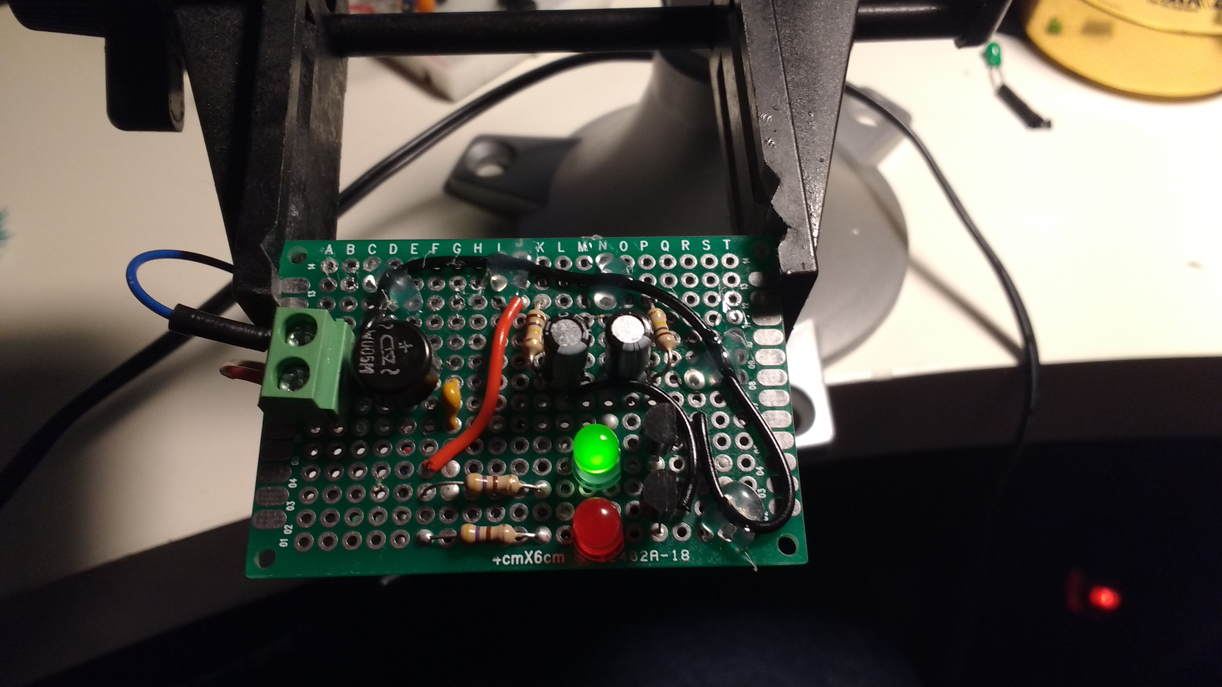
It’s a simple two-transistor astable multivibrator that alternates between the red and green LEDs at around 2Hz. Everything to the right of the red wire is pretty bog-standard: 5% tolerance 470 ohm current-limiting resistors for the LEDs and 100k ohm resistors for charging the 10uF capacitors. Two BC548 transistors do the switching. Some 24 AWG wire connects parts too far apart (or awkwardly placed) for component leads to reach.
In retrospect, I could have laid things out better, but she didn’t mind. The only major thing I’d change is using ceramic capacitors instead of electrolytic, as I’d like to keep this circuit around until she’s older and have it still work without the capacitors drying out, but I didn’t have any 10uF ceramics at hand. I’ll order some, have her pick them out, and swap them out.
On the left is a simple terminal block for connecting a power supply. I wanted the circuit to be robust in terms of polarity, so I used a bridge rectifier so it can operate regardless of how the DC power supply is connected (I could have added a filter cap so AC could be used too, but I don’t have any wall warts with AC out, and she likes batteries, so this was not a major design consideration). I could have used a cheap diode, but the bridge rectifier uses Schottky diodes and so drops only 0.6V compared to a 1N400x’s 0.7V, plus it means the circuit will work (rather than simply not be destroyed) regardless of how it’s connected, so that was an easy and robust choice.
A 50mA polyfuse provides protection from faults (important when using old cellphone Li-Ion batteries as a power source). All the exposed underside contacts of the unfused section (i.e. terminal blocks and rectifier) are liberally coated with hot glue for insulation, with the jumper wires on the top and bottom tacked down with hot glue as well. All solder and components are lead-free, with burrs and other sharp points on connections filed smooth for minimal danger.
My daughter loved picking the components out of the parts drawers, listened attentively while I explained what they did and how they work, and helped me put them in the correct places on the breadboard. After things worked and she (later) went to bed, I moved the same parts over to a protoboard for a bit more durability. Now she’s running around the house waving it (and the 1000mAh cellphone battery stuck to the bottom with double-sided tape) around, blinking it at her baby brother, and integrated it into playing with her other toys.
This makes me happy.