I have a bunch of eBay-sourced DC-DC converters that I use for a bunch of purposes around the house. Most are ordinary “LM2596” (in scare quotes, as most seem to be clones: they’re marked as LM2596 and generally work well, but have different switching frequencies. Supposedly this is an issue with such things.) buck converters configured as adjustable, constant voltage power supplies where the output voltage is set by a multi-turn potentiometer. Very handy.
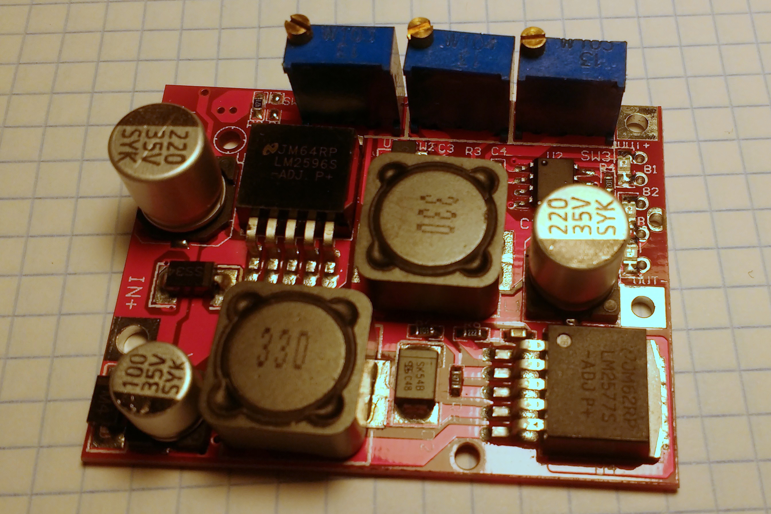
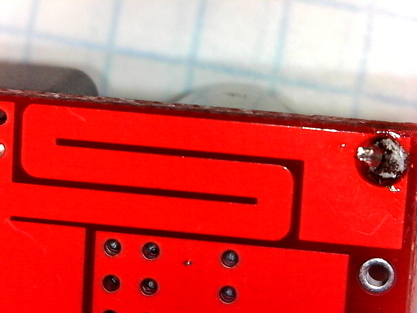
Others can be used in either constant voltage mode or constant current mode. For the latter, a serpentine strip of PCB trace acts as a low-value sense resistor. An LM358 dual op-amp integrates the difference between the voltage across the trace and a voltage set by a potentiometer, with the output connected to the regulator’s feedback pin via an LED so you can tell when the regulator is in constant current mode. Another potentiometer sets when the “charging” LED lights up; this is purely cosmetic, and the LED turns off when the current through the regulator drops below the setpoint set by the potentiometer.
Caleb Engineering has an excellent teardown of such a regulator here.
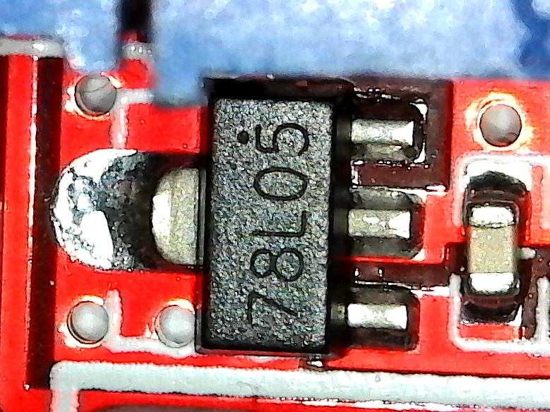
Here’s a few pictures of mine:

Today, I wanted to use one of these modules to charge some supercapacitors in a controlled way, so I grabbed one of the buck modules, set the voltage limit to 2.6V (to stay within the 2.7V maximum limit of the supercapacitor) and the current limit to 500 mA. For testing, I connected the input to a 12V supply and everything worked fine.
I then connected the input to a 5V supply, which is more convenient for most things I do, only to watch the regulator go into current-limiting mode and push out 3.5A (!!). The current limiting potentiometer did nothing, even when turned all the way down to zero. The capacitors and the LM2596 started getting toasty warm (uh-oh), so I unplugged things to investigate.
It turns out I forgot a crucial detail: the op-amp is powered by a 78L05 5V linear regulator connected to the input voltage. Although the LM2596 switching regulator used to power the load has a dropout voltage of less than a volt (and the 2.4V difference between the 5V input and 2.6V output is perfectly suitable in any operating condition), the 78L05 regulator for the op-amp requires at least 7V input to stay in regulation. Supplying it with only 5V input meant the output voltage was less than the regulator needed, and so the feedback loop was broken and the LM2596 tried its hardest to pull the voltage up to 2.6V, maxing out its output current.
As soon as I connected the input of the module to a 9V or 12V supply, it worked great, since the 78L05 had a sufficient voltage difference to stay in regulation.
It’s worth being aware of this issue, particularly if your input power supply doesn’t have a lot of “oomph” behind it: if the input voltage ever drops below 7V (such as when supplying a heavy load) the 78L05 will drop out of regulation and the LM2596 will draw even more current, thus holding down the input voltage and preventing the system from recovering. Fuses are your friend in such conditions.
To prevent such issues, you might consider using some of the buck-boost modules (which are also available in constant voltage only, or CV/CC variants). They use a boost converter to first step up the voltage to a higher voltage (I have several different ones, some with LM2575 boost converters, while others have XL6009 chips, both boost to around 28V), which the LM2596 then bucks down to the desired output voltage. The 78L05 can handle input voltages up to 30V and the op-amp currents are low, so it works fine. There’s some loss of efficiency when using two converters instead of one and the maximum output voltage is slightly lower, but I haven’t found any edge conditions in the buck-boost configuration that cause bizarre failures like with the buck-only converters — one such buck-boost constant current supply has been driving the IR LEDs in my DIY babycam for more than a year from a 5V input without any hitches.
Edit: Although the constant current buck-boost modules commonly found on eBay will work fine with lower input voltages because the linear regulator gets its input from the boosted voltage from the first stage, it seems they cannot start up properly if they’re connected to a dead short when they’re first connected to input power. The switching regulators go into current-limiting mode and the linear regulator doesn’t get enough voltage to properly start the op-amp for constant current mode. I blew a bunch of fuses testing this (better than blowing up components!). Once the switching regulators have started up and the linear regulator is in regulation, the constant current regulation works as expected.
This issue could have been avoided by adding two resistors and a small capacitor to the ON/OFF pin on the LM2596 buck regulator for a delayed startup. This would keep the buck regulator offline for enough time that the boost and linear regulator, as well as the op-amp, would start up and be ready. Alas, due to the layout of the boards from the eBay suppliers, modifying the existing board isn’t really feasible.
In short: the buck-boost regulators with constant current regulation are better in general since they have fewer failure modes once they’re running, but the output current needs to be limited for a few moments when they’re first connected while the constant current regulation circuitry comes online otherwise they just max out their current. Not what you want. Adding some inrush limiting circuitry (e.g. an NTC thermistor and, optionally, a bypass MOSFET for higher efficiency) would work great.
Here’s an example of the buck-boost boards that I like, even with the above-mentioned limitation.