A while back I needed to interface a GPS timing receiver that only has an RS-232 serial connection with one of my Raspberry Pis. The Pi only supports TTL-level serial and only tolerates voltages between 0-3.3V its the UART pins.
Enter the MAX3232, a chip from Maxim Integrated that converts between RS-232 and TTL serial with supply voltages from 3.0 to 5.5V. It produces “true” RS-232-level voltages (both positive and negative) using built-in charge pumps and some small external capacitors. Just the ticket for what I needed.
Alas, the MAX3232 isn’t really something one can run down to the local electronics shop (and there isn’t any such shop where I live in Switzerland, as far as I know) and pick up. Typically it’s purchased by manufacturers in quantity from major suppliers. Hobbyists like myself need to turn to the internet where such things are available in abundance for cheap from China, though one must be wary of counterfeits. Of course, I could order from legitimate Swiss distributors, but small-quantity pricing and shipping are extremely high (>$10 USD per chip!) compared to major US distributors like DigiKey and Mouser.
In my case, I ended up buying a few boards like this one from an online vendor in China. The listing specifically states it had a MAX3232 chip. My thought was that if it was a legitimate chip, cool. If not, it’d be an interesting experiment and I’d get some cheap DE-9 connectors out of the deal.
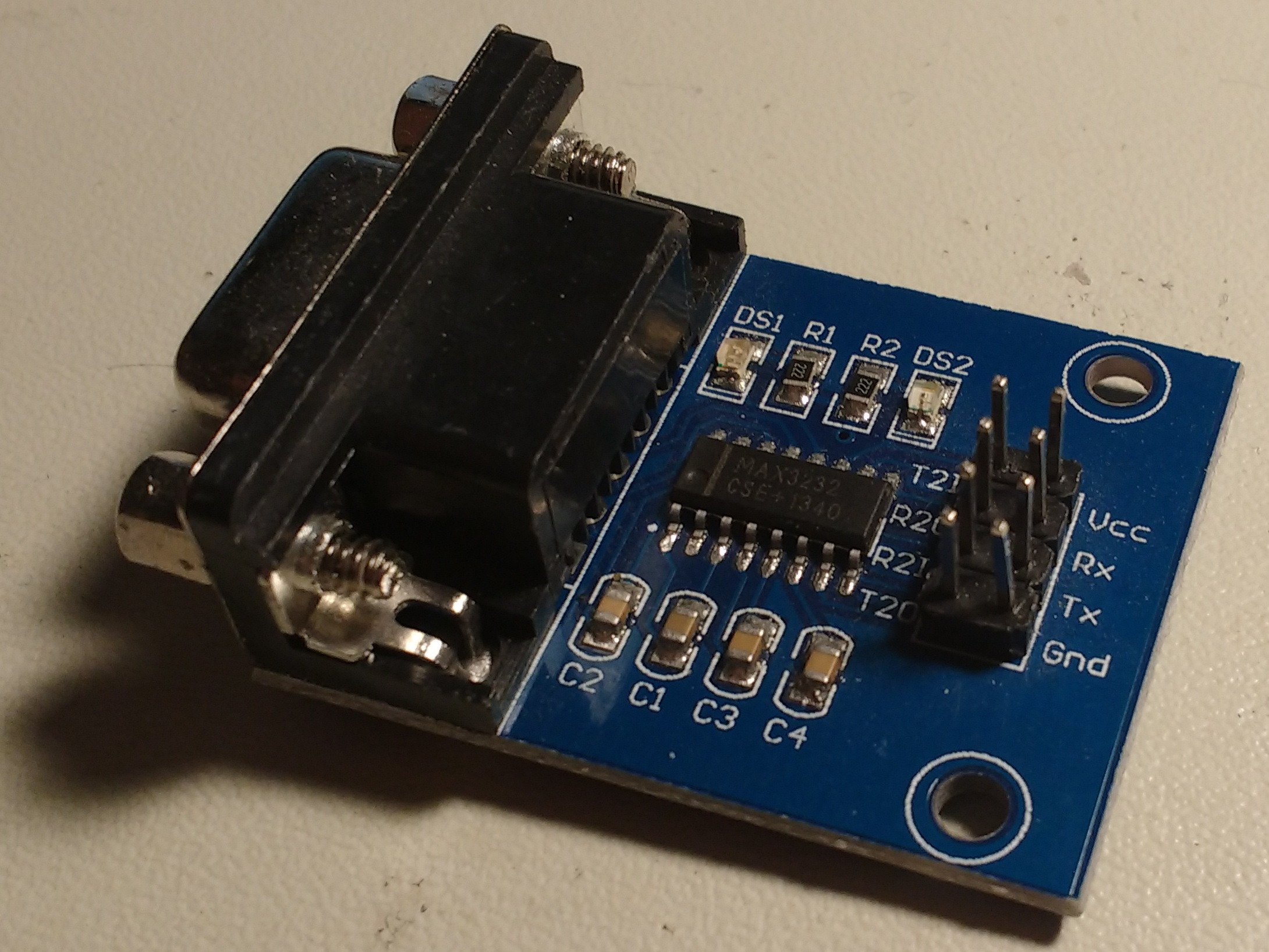
To the naked eye, everything seemed to be reasonable. The chip did have markings identifying it as a MAX3232 (falsely, as I later discovered; read on!). The board worked and the chip functioned within the specs in the Maxim datasheet and it even broke out the chip’s second RS-232-to-TTL channel on the header pins.
However, the first board failed after a few weeks, drew significant current, and dramatically overheated. By “overheated” I mean “blister-raising burn on my fingertip”-level-hot. Also, the data-transfer LEDs were glowing faintly all the time rather than flickering on and off when data was flowing.
Figuring this was just some bad luck on my part (this is before I got the anti-static mat on my desk), I swapped it out for another board. I was particularly careful with anti-static precautions, and put the board over a small glass container just in case it overheated and caught fire. Although it didn’t catch fire (thankfully!), it did fail after a few weeks and overheated just like the first one.
Ok, so something’s going on, but what? Since the chips had obviously failed, I figured I couldn’t harm them with some ham-fisted SMD desoldering, so I took them off their respective boards.
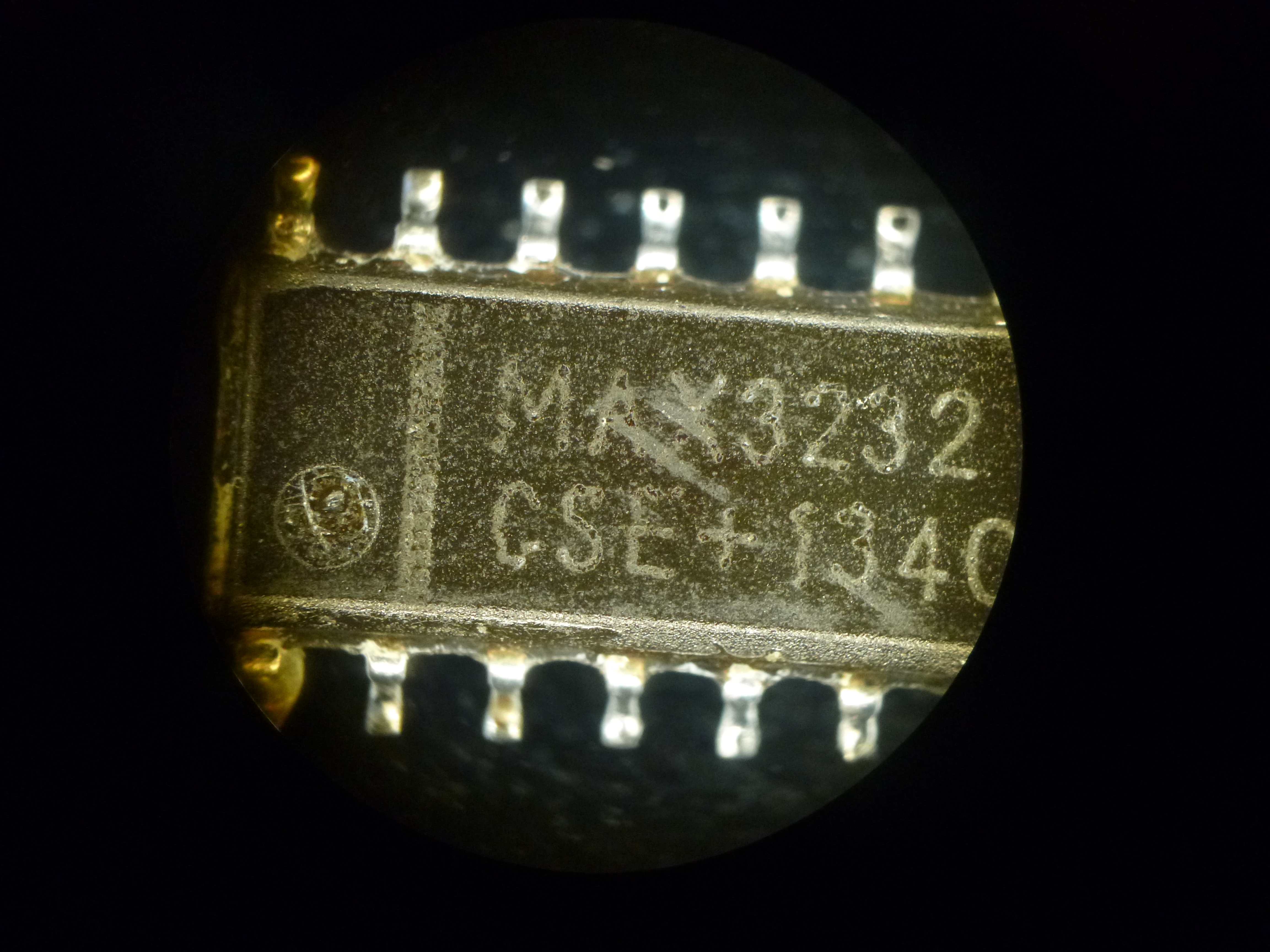
Here’s the results of my handiwork, as viewed under a petrographic microscope in the lab (I used a handheld camera aimed through the microscope eyepiece for all the microscope photos, hence the weird vignetting at the edges):

All right, quit laughing! De-soldering SOIC chips using a handheld soldering iron is no fun.
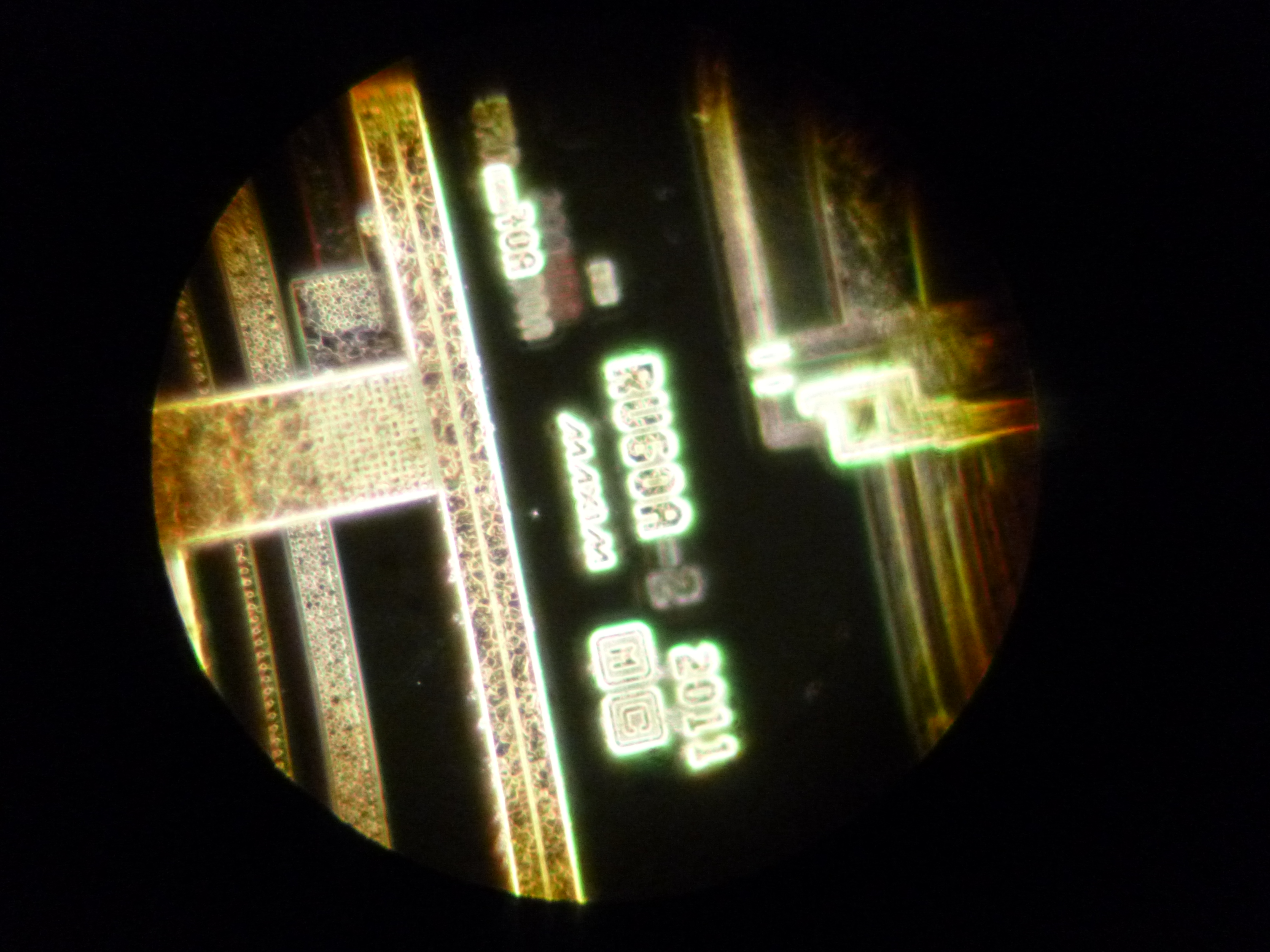
Anyway, the markings are inconsistent and seem pretty low-quality. Definitely not something I’d expect from Maxim. For comparison, I had ordered a free MAX3232 sample directly from Maxim (thanks, guys!) and it arrived a few days later. Here’s the legit chip:
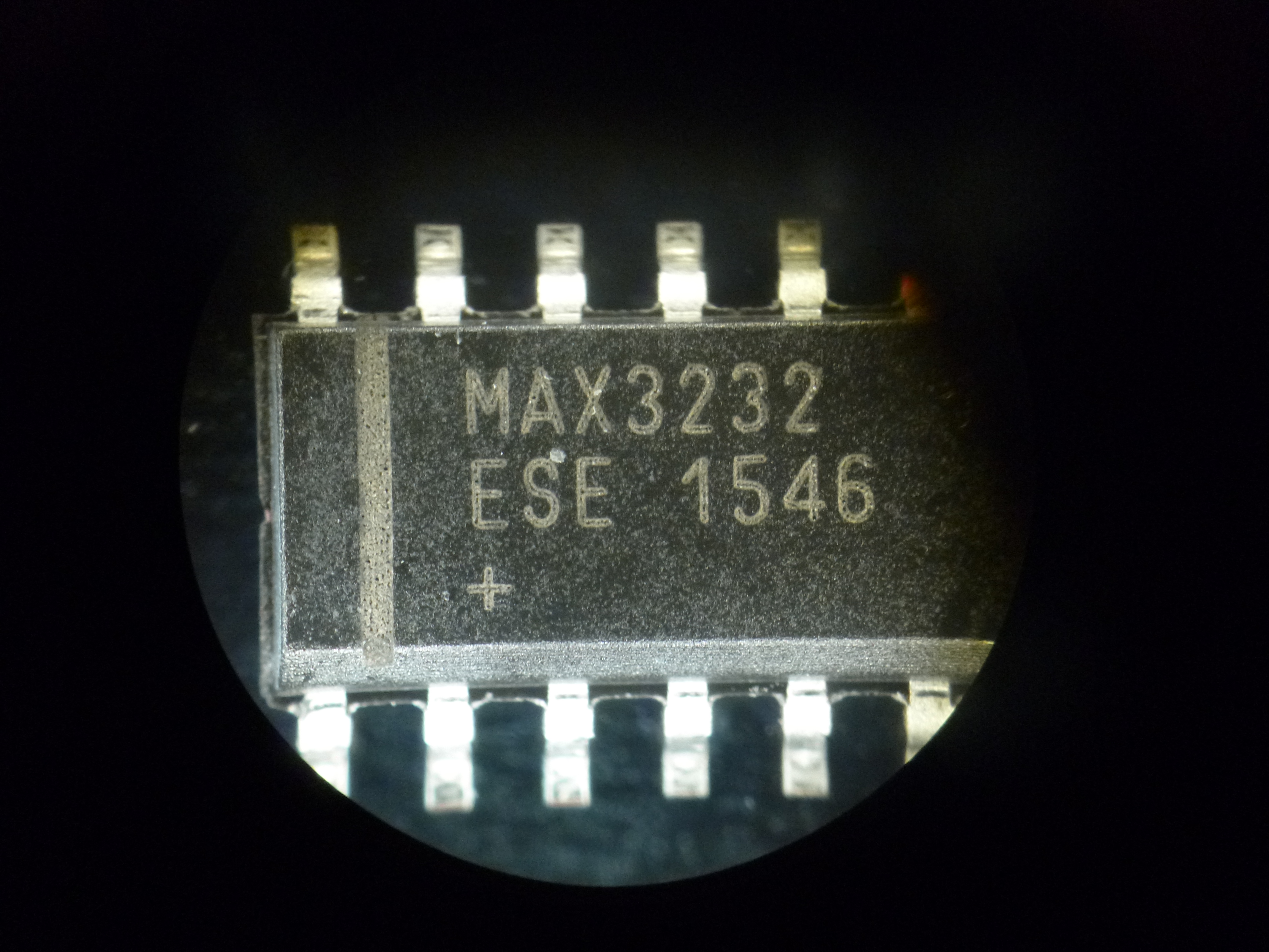
According to the date code, I ended up killing this chip in the name of science about 2-4 weeks after it was made. Sorry, little guy. Anyway, you can see the markings of the real chip are distinctly different from the fake chips. The differences are striking even with a handheld magnifying glass: the real chip has distinct laser-etched markings with a textured surface. The fake chips have much “weaker” etching with a much flatter, duller surface.
Next, I decapsulated all three chips (two fake and one genuine) by dissolving them in hot nitric acid followed by an acetone wash and a few minutes in the ultrasonic cleaner. Don’t try this at home (or at least not in my home!): I did it in a controlled environment with a fume hood, proper ventilation, protective gear, etc. Zeptobars and the CCC have some interesting guides on how to do this if you’re interested. Be careful.
Alas, I wasn’t able to do the preferred method of just dissolving the package over the silicon die itself. Instead, I decided to dissolve the entire chip package, legs and all. Interestingly, the genuine one dissolved much more rapidly (but at a consistent rate) than the fakes; the fakes resisted the acid for nearly an hour, then quickly dissolved in a few minutes. The package seemed to be the same blackish epoxy that most chips are encased in, so I have no idea why they would behave so differently in acid. Any materials-type people have any ideas?
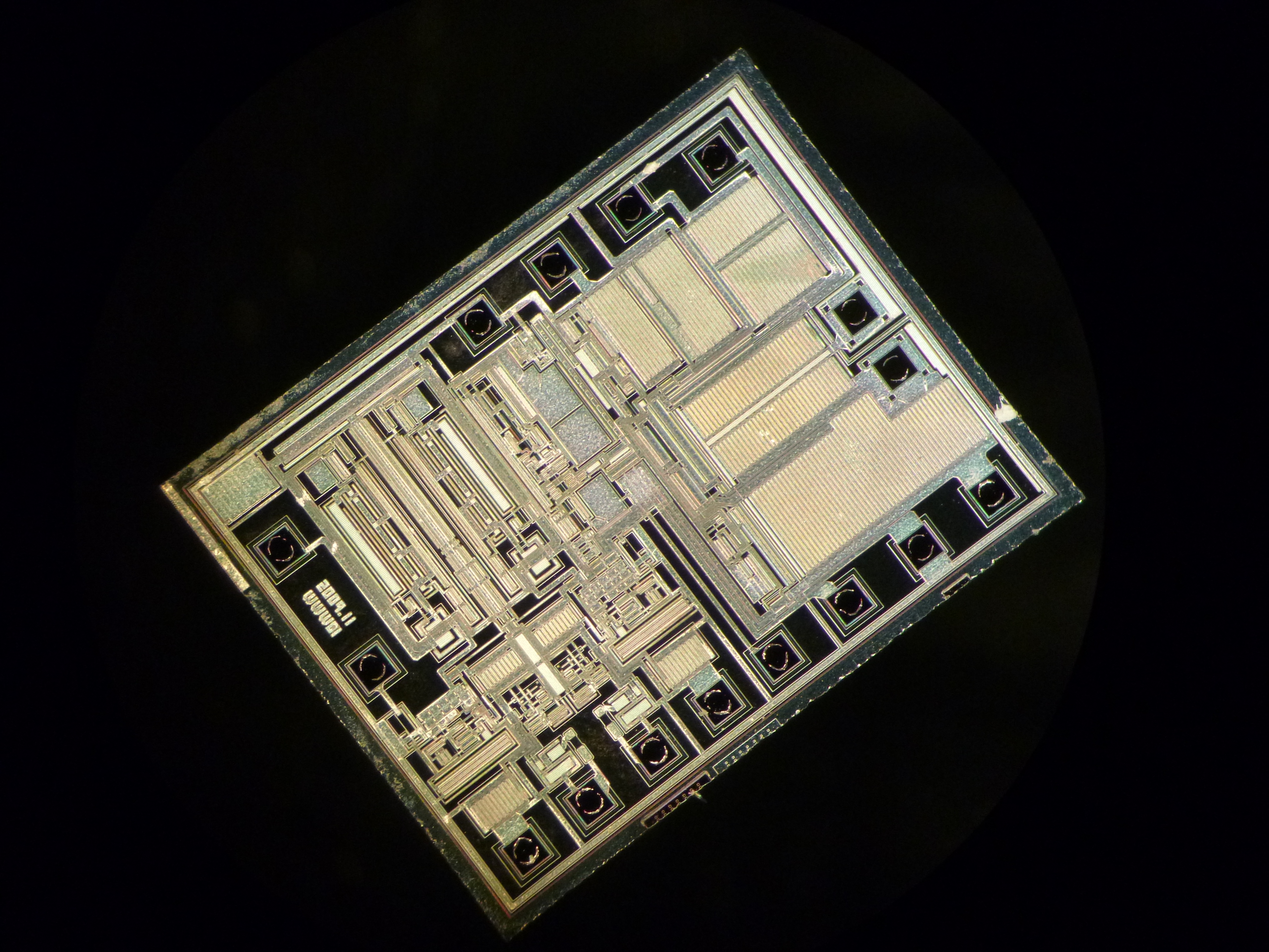
Here’s what the real MAX3232 die looks like:
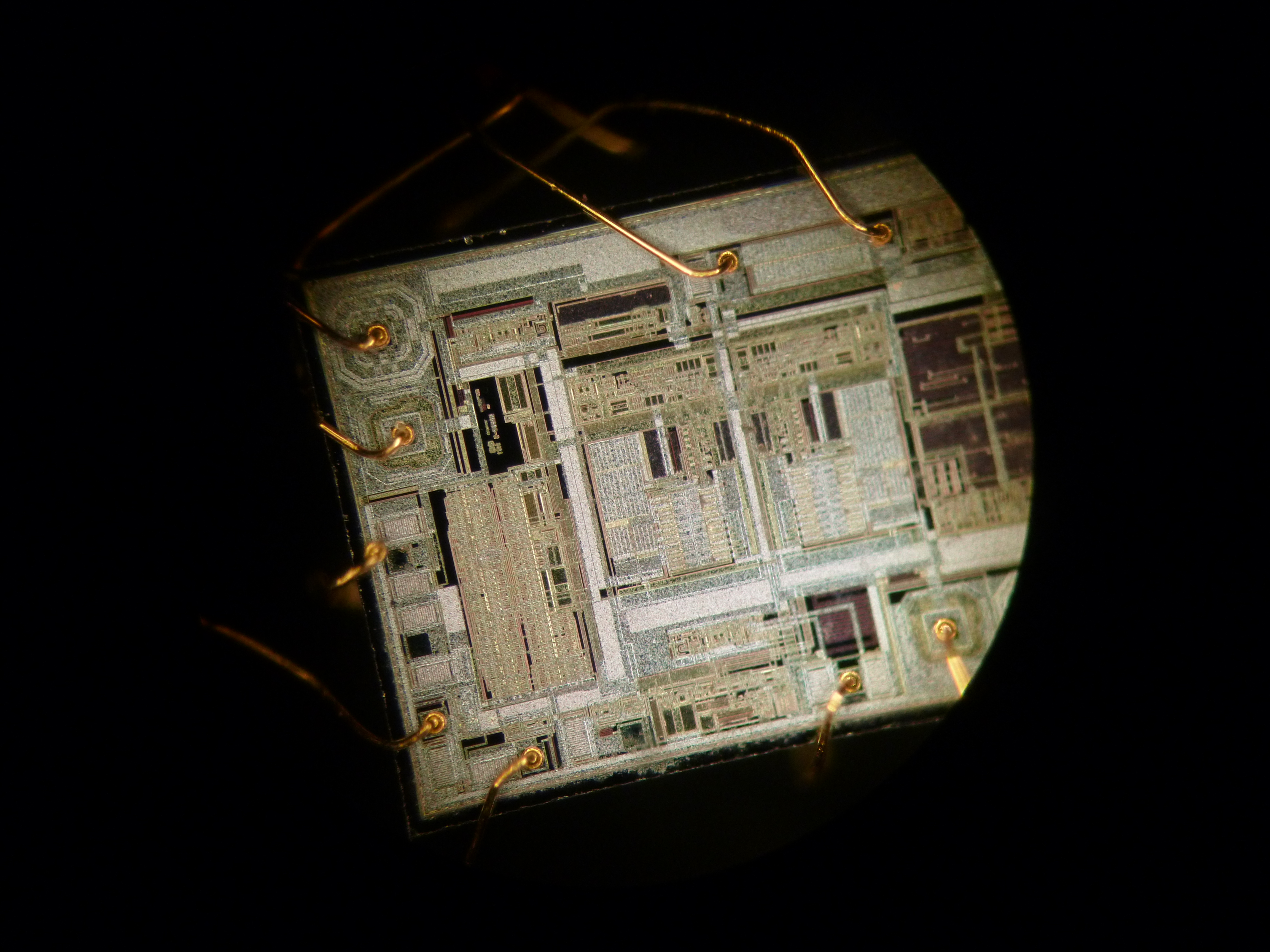
Note the gold bond wires are still attached and didn’t dissolve in the acid bath. I’m not a semiconductor expert, so I can’t tell you what the actual regions of the chip actually are, but it’s a pretty picture and serves as a good reference for comparing the others. Also, the genuine die is about 50% longer than the fakes so it couldn’t fit entirely in the field of view of the microscope.
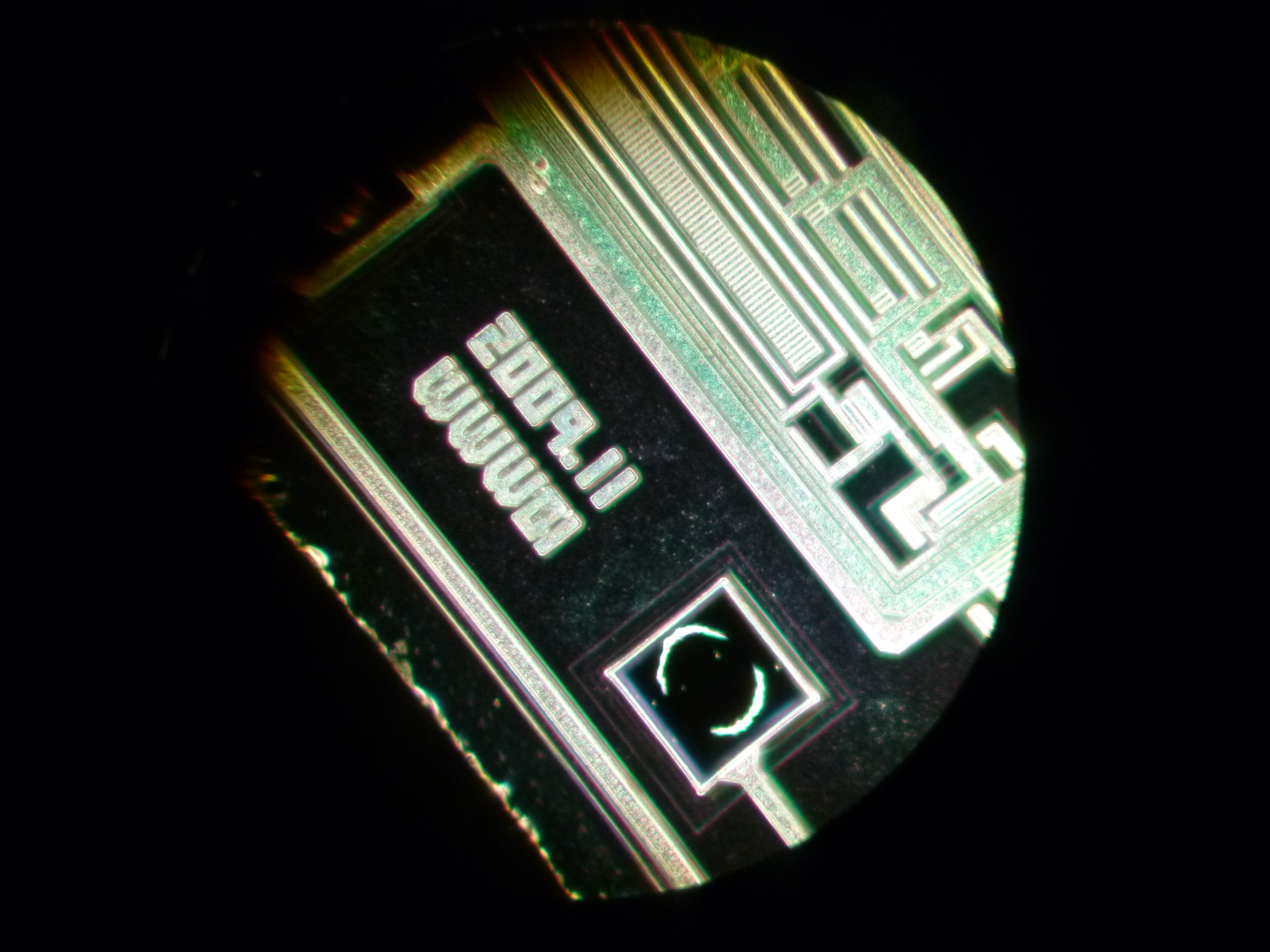
Here’s a closeup of the “Maxim” marking on the genuine chip as well as a date code. Presumably it refers to when the chip design was finalized.
Now, let’s look at the fakes. Both fakes were, unsurprisingly, identical.
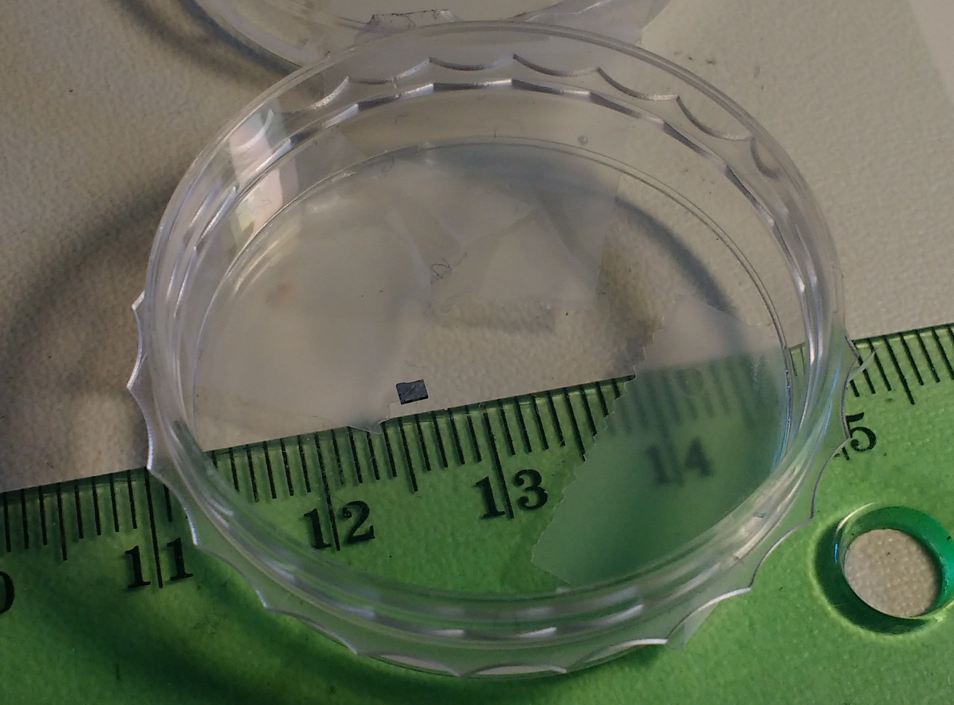
Without magnification, the dies are pretty small and it’s hard to make out any detail.
Under the microscope, we can see the die quite well.
The above photo was taken at the same magnification as the genuine MAX3232 die photo: you can see the fake die is much smaller, has a much different appearance, and didn’t use gold bond wires. Whatever metal was used for the wire dissolved away in the acid.
Both chips had the same markings: they appear to have been designed in November 2009, and the marking on the second line appears to be “WWW01” (though I’m not sure if it’s the number zero or the letter “O”). I’ve had no luck figuring out what that means.
As I mentioned above, I’m not an expert on low-level chip design or failure analysis and I was unable to find any obvious-to-the-layman failure in the chips that would have resulted in them passing significant current and overheating. Any ideas?
Pete
Nice work.
An interesting thing about the fake is that it does not have what is typically referred to as a boilerplate. The 70A on the Maxim part is part of one. The 70 is the gds layer number and the A denotes revision. The A matches the A in the Rxxx-A number too.
The first tack I would take debugging the failure would be to ohm out the pins of the part before turning it on and after it fails. That is if you have a supply of chips which has always been the case when I have done this sort of stuff. This lets you narrow down the search. Most likely a gate was over stressed. You probably won’t be able to see that. There do not seem to be any signs of the metal lines fusing open. Hope that is helpful.
Hi Gregg,
Thanks for the response!
Interesting details about the boilerplate (or lack thereof in the fake ones). Do you have any links where one could learn about such notations? I’m familiar with “chip art” on dies, but other than manufacturer marks, date codes, and obvious version numbers, I don’t know much about other more subtle markings.
I’m really curious who actually made the fake and was hoping someone could ID the manufacturer based on the markings.
As for debugging, that’s a good idea. So far the replacements (either transplanted MAX3232s hand soldered onto the cheap Chinese boards after the fake chips blow up, or other reputable modules with genuine Exar SP3232s) have been going well, so I haven’t had reason to tinker with the few fake MAX3232s I have left. If the need arises, I’ll definitely do some more poking around.
Thanks again, it’s been very helpful!
Yes, black market or informal dealers, can give you a headache if parts are acquired from recovered assemblies or packed from scrap parts due a wrong production. I had to lead that issues on manufacturing companies, mainly on small ones.
The wires are aluminium on the (bad) copies, that’s why they dissolved.
Can take high res photos if that’s of interest (ex: http://siliconpr0n.org/map/cbm/65ce02/r1_mz_mit20x/)
Neat, that looks really cool.
I’d be happy to send you one of the fake dies if you want (I lost the other fake one and the real one since they fell out of the tiny container they were in). Drop me an email: pete[at]heypete.com.
“Alas, the MAX3232 isn’t really something one can run down to the local electronics shop (and there isn’t any such shop where I live in Switzerland, as far as I know) and pick up. Typically it’s purchased by manufacturers in quantity from major suppliers. Hobbyists like myself need to turn to the internet where such things are available in abundance for cheap from China”
The MAX3232 is easily available from both Reichelt and Conrad, in SMD and DIP cases. I have no doubts that both buy them directly from the manufacturer. Pollin has a complete module with a MAX3232, DB9 connector, pin header and two useless LEDs for china prices (order code 810 358; 2,95 €). Pollin also offers a kit with the older, 5 V only, MAX232 (order code 810 036; 3,95 €). Unlike the module, the kit has the CTS and RTS handshake lines connected to the MAX and omits the LED crap. Use the kit, swap the MAX232 for a MAX3232 (the MAX3232 accepts the larger caps for the MAX232 just fine – read the data sheet) and you get a universal level converter operating from 3 to 5 V.
Hi Tux,
Indeed. Let me clarify a bit: I’m not saying that the parts are wholly unavailable in Switzerland (as this is clearly not the case), but rather that they’re (a) not readily available at retail (as they are in, say, the UK at Maplin, though at a bit of a markup) and (b) buying one or two from Conrad gets quite expensive with shipping (CHF 4.70 for the chip + CHF 8.95 for shipping from Conrad). Importing from online vendors in the EU can get extremely expensive for small orders due to shipping costs, import duties, and customs handling fees.
Ordering from Maxim directly is feasible, but shipping is USD $15 and so is prohibitively expensive for small quantities. Definitely worthwhile for medium quantities, and one is assured of genuine chips.
The boards from Pollin look interesting, but are they actual Maxim (or TI or other genuine second-source) chips or are they basically reselling Chinese eBay/AliExpress boards? Either way, import/customs handling fees kick in above a certain limit.
It’d be great if there was something like Maplin (UK) or RadioShack (US) in Switzerland where one could order small quantity parts (at a higher per-unit cost, of course) but with cheap shipping, short waiting times, and no import duties.
That said, thanks for pointing out several different vendors. It’s always nice to know what options are available; being an American ex-pat I often don’t know the names of various mail-order vendors, so I don’t know where to start looking.
Hey Pete! Nice write-up. You have a few options to source parts locally if you live close to Zurich. On a completely unrelated note, your call sign somehow rings a bell but I can’t figure out why right now. Regards! Matt
Hi Matt,
Thanks!
Out of curiosity, what are the shops in Zurich? I’m in Bern, but having a reasonable domestic supplier would be nice even if I have to pay for shipping.
Which of my call signs rings a bell? I occasionally do digital modes on HF from Switzerland (usually JT65 and JT9 on 20/40 meters) and am sometimes on /r/amateurradio on Reddit. Alas, my apartment doesn’t really permit visible antennas, so I have some speaker wire run around the inside of the ceiling as well as a tiny 28AWG random wire antenna I occasionally toss out the window. Neither of which is that great, but it gets me on the air (kinda) if conditions are OK. In the US I mostly operate on handheld UHF/VHF in Massachusetts and the SF Bay Area when I visit family there.
If you’re in Europe and want to chat on HF sometime, let me know.
Hi Pete. In the vicinity of Zurich, the options I am aware of are: (1) Distrelec, where you can order online and pick up the parts two hours later at no extra cost. (2) Conrad where you can do the same. You don’t even have to pre-order if they have the parts on stock. Also they have “free shipping days” more or less regularly, where they drop any shipping fees. (3) The BASTLI (some ETH EE student group who has an on-campus lab with lots of awesome tools and instruments) has parts on stock that they are selling for extra-curricular projects. (4) There’s also a store called Pusterla in Zurich. It’s old-school and prices are relatively high, probably the closest to the brick and mortar thing you are looking. Still potentially a good option if you need some basic parts quickly. Such stores are hard to come by these days (I remember that we had three of them in Zurich when I was a kid, now it’s down to the one) but they exist, not only in Zurich. By chance I found one in Gretzenbach, 15 minutes from where I live. I’m also ordering from digikey about once per month. You can piggy-back on my order if you want but that would require some planning.
Now that you mentioned Bern, you might be somebody I met on reddit. Are you the guy with the air-tight windows? If so, I think we wanted to go for a beer or something. We should do that :-).
Very cool, thanks for the info. I may be interested in going in on some Digikey orders in the future.
As for the windows, yeah, my windows have gaskets on them that makes it a pain to run antennas and whatnot outside when they’re closed in winter. I just looked through my reddit messages. Are you megapopo/MrCircuitMatt? And yes, beer is always a good thing. I’ll let you know the next time I’m up in Zurich and have some time to spare.
Yeah that’s me. 🙂 I just started a two-week holiday, maybe that’s the opportunity to meet. Also I’ll order from digikey in the next few days; in case you need something on that order, now-ish would be a good time to let me know.
Component test engineer here. I am happy for your plight (keeps me employed) the mention above about overstressed gate is spot on. Check your passives are correct. I recently got a batch of 2813 addressable leds that they put the board in upside down or something. Sometimes the fakes are only off a little and you would never notice. Extra few uA input bias current here, extra ppm/c there. But this looks like something icky for sure.
Good write up btw.
Good idea! I still have some of the fake boards here, so I’ll check the capacitors. Alas, the little SMD caps aren’t labeled but I can desolder them easily and test them directly.
Speaking of tests, I was also testing some Chinese DS3231 temperature-compensated real time clock modules (useful for the Raspberry Pi when network access is dodgy). Surprisingly, they worked perfectly: the temperature compensation works great, and they’re within 1ppm (usually better, though they’re specced to 2ppm). I counted their 32kHz outputs using one of the hardware counters in an AVR microcontroller and used the PPS output on my Trimble Thunderbolt GPSDO (<20ns rms error on the PPS signal) as a gate to precisely mark one-second intervals. I did measurements ranging from 10 seconds to a few days, and they're right on the money. That was a fun test.
Both the bond wires and the Al bond pads were etched during decap, not normal with fuming Nitric. The bond wires were definitely Au: the impression left on the bond pad is round which indicates a ball bond which used with Au bond wires. Al bond wires are ultrasonically welded to the Al bond pad which leaves a more rectangular impression. Al bond wires used in plastic package will eventually fail due to mechanical stress from the plastic while Au bond wires are much more ductile and can survive the stress. The Al metal leading from the bond pad next to 2009.11 marker looks open, can not be certain with this photo. My guess would be latchup induced overstress of this metal trace. Looking at the die layout the output and input xsistors are packed together compared to the Max232 die which can make a die easier to latchup. Overheating during latchup could also accelerate intermetallic formation at the Au ball/Al bond pad.
Hi, thanks for the feedback and your valuable insight!
I was using ordinary nitric acid, not fuming nitric, as that’s what the lab had in stock. All three chips were in the same petri dish at the same time during decapping, yet the gold wires on the genuine die didn’t dissolve but the wires on the fake ones did — that leads me to think (possibly erroneously) that the bond wires on the fakes weren’t gold.
Is it possible they used copper bond wires? From what I’ve read, copper wires use ball bonding and dissolve in nitric acid.
I still have one more of the fake dies (hopefully one in the photo) and could always decap another that I have lying around here. If you can highlight where you think the metal is open near the 2009 mark (I’m not seeing it, but I may be looking at it wrong) I can try to look at it under higher magnification and post more photos.
Indeed Cu bond wires could be used as could Ag bond wires, both would be affected by nitric acid. I am not as familiar with decapping with those bond wires, a quick survey states either plasma http://www.jiaco-instruments.com/case-study-and-publications/icept-2011-MIP-plasma-decap or a mix of sulfuric and fuming nitric https://www.researchgate.net/publication/3425149_Acid_Decapsulation_of_Epoxy_Molded_IC_Packages_With_Copper_Wire_Bonds. I will ask some colleagues for their suggestion. The Max3232 die is 3u CMOS Al/1%Cu metal with Au bond wires so it was easy to decap. Normally the packaged is milled a bit over the die, shallow enough not to affect the bond wires, and heated on a hot plate. Then drops of fuming nitric are slowly applied to the milled area, rinsing periodically with acetone, until the die is exposed. This better preserves the die, bond pads and bond wires.
But you can do so electrical analysis of the device to try to pinpoint the failure without decapping. if the failed device still consumes a lot of current you likely have shorted junctions due to metal spiking through source or drain junction. If there is little to no current drawn then you have some open metal traces which, depending on the number of metal layers, you may see visually. Quite often the area(s) of the die that overheated during failure will have packaging residue remaining. If you have access to a curve tracer you can look at the I V characteristics of the power supply pins and the output drivers. This is best done comparing to a good device but sometimes it is an obvious short or open.
The metal trace leaving the bond pad nearest to the ’11’ of 2009.11 seems to go nowhere which either is an open or a contact or via that I can not see from the photo. The drivers on the opposite of the die seem to have some packing residue remaining.
Good Luck!
Cool, thanks for the info!
I’m familiar with the normal way of decapping with only a few drops of acid at a time. However, I didn’t have access to a drill/milling machine at the time but did have access to an abundance of standard nitric acid and a hotplate (no fuming nitric acid, alas). Short of hand-scraping out a pocket for the acid with my pocket knife (I’m much too lazy to do that), dissolving the whole chip seemed like the way to go.
As for electrical analysis, the failed devices consumed a lot of current and got extremely hot: it’s likely that there’s some internal short or other similar failure.
Very interesting details about the packaging residue likely remaining on overheated parts of the die. That will greatly help in future examinations of other chips I plan on doing.
Out of curiosity, is there any sort of useful reference works/textbooks/guides for analyzing chips visually, determining what different components are, and seeing how they might have failed? I have a background in physics, not electrical engineering, but am a quick study.
It should not be said that the chinese chips are fake. It is just a generic MAX232 part number. There is no fake brand label on it.
I disagree. There are no generic MAX3232s. The only legitimate manufacturers of MAX3232 chips are Maxim Integrated and Texas Instruments.
Since whoever made these chips is not Maxim or TI and they applied the “MAX3232” markings to the chip, the chips are fake. You’ll note that they attempted to put the date code, plus sign, and stripe in similar places on the chip as the real one. This indicates they were trying to deceive people.
Sorry, these chips are fake. Moreover, they’re bad, dangerous fakes.
Yes, I know the conversation in question is over 3 years old..
Can I ask what your using as a basis for the claim that only Maxim and TI can make a MAX3232 IC?
Normally to stop the usage of a name or mark requires a trademark. While the Maxim name and their logo are both trademarks, there is no trademark on the usage of MAXxxxx, a white stripe on a chip(I’ve seen it on at least 1 each of Intel and Motorola chips).
Wither it was a Maxim trademark or one they were using under license(MAX is a trademark of Altera, I just don’t know which class), I can guarantee you that Maxim would make note of it, at least on the datasheet and on their Trademark page at a bare minimum. As an example, from the first page of the MAX3232 datasheet, we know that MegaBaud and UCSP are both Maxim trademarks. So it’s a fairly safe assumption that MAXxxx is not a trademark. Unlike a copyright, a trademark must be announced and defended to keep it useful. (There is no trademark claim on the TI datasheet either(I own both types))
A lot of companies make compatible chips (ICL3232, ST3232, etc), but the majority of makers use their own prefixes for this.
The weird part here is that your Maxim chip does not have the Maxim logo on it. I’m too lazy to go dig out any SMD parts, but at least 3 of their DIP parts show the logo. They range in size from a DIP8 to a DIP24.
Is the other companies actions illegal? No. Is it unethical, maybe.
Sorry about the screed.
GB Clark
AE7OO
Hi GB Clark,
Good question! Speaking only as an amateur, individual, non-lawyer, and non-representative-of-any-company, I was going off the Wikipedia entry that described Maxim making the chip originally and TI making compatible chips using MAX232 as a part number. As you say, other companies use other x232 (e.g. ICL232, SP232, etc.) part numbers that are pin-compatible. (To be fair, I think that TI should have used their own TI-specific part number to avoid confusion.)
Digi-Key, my go-to for legitimate components, lists only Maxim and TI as manufacturers of the MAX232.
While you’re certainly right that a white strip on a chip isn’t a Maxim-specific trademark, the fact that they combined several aspects of the Maxim chip (e.g. the MAX prefix, the white stripe, the Maxim-specific device identifiers like ESE, CSE+, etc.) and didn’t put some other marking to distinguish that it’s not a Maxim chip (like their company name, logo, etc.) is particularly deceptive to me.
Again, I’m not a lawyer, don’t work in the semiconductor industry, and have no connection to any of the companies above. I am neither prepared nor qualified to discuss the legal specifics, but I do know that selling chips that have or attempt to have the same markings (even if those markings are not trademarked) as brand-name chips, especially when the copies are not of similar quality, performance, reliability, etc., don’t carry a manufacturer’s mark, have no datasheet listing specifications, etc., seems to me to be both deceptive and unethical. Blatant counterfeiting (where actual trademarks and brands are reproduced without permission) is already rampant in the chip industry, so trying to barely squeak by with the corporate equivalent of the kids “game” of “I’m not touching you! I’m not touching you!” isn’t a good thing either.
If a company wants to make an RS-232-to-TTL converter chip, awesome. I’d happily consider buying it. But I’d much rather see them make it under their own name and part numbers to clearly differentiate it from existing products than copy the markings, identifiers, and design elements of those existing products.
I hope that clarifies my position and reasoning, and I hope that you don’t find my position to be horribly misguided or misplaced.
Greetings,
No, I have no problems with your position regarding their actions.
I was just making the statement that technically they aren’t fakes. While some of the stuff
is a little shady(or more than a little), unless the datasheet’s or sales copy claims they are Maxim parts, or if a specific part is showing a Maxim logo, then they clones. And not all clones react the same way.
Unless I’ve found out otherwise, I treat all boards/chips out of China as being grade B or less. As an example, the infamous Blue Pill STM32F103 boards. While some of these maybe fake, I have not had one(and I’ve ordered over 50 of them) fail to meet datasheet criteria or had markings that scream fake. And I know that they were not all using the same die either seeing how they were all marked as being C8’s, which should have 64K flash, but some had a usable 128K flash(like the CB’s). I’ve had “real” ones(sampled from ST) show the same properties, so that by itself does not mean much.
As far as TI using the MAXxxxx nomenclature, if I had to guess, some BIG customer required a second source of the part(s) and so TI is using Maxim’s design to supply it. In most cases that I’ve seen(Not that many I’ll admit) a second source has to be using an identical design, otherwise you can’t trust it to respond to corner cases/stresses the same as the first part.
GB
AE7OO
chinese chips are fake don’t think so. its just only generic MAX232 part number.
For reasons I’ve explained above, I disagree. Using the same part number and similar markings as Maxim on a part not made by Maxim nor meeting the same specifications is deceptive even if it’s not explicitly illegal.
Perhaps I should turn the question around: why do you think it’s acceptable for manufacturers to use the same part number and markings on a chip that’s not the same as that made by the original manufacturer? How would that benefit the customer?
Very interesting report, I’ve just run into 10 of these little Chinese fakes and I’m about to review the seller posting a pic of my burnt fingertip. In my case those who didn’t burn just did not show any production of positive and negative voltage on pins 2 and 6, but this is erratic; cycling power on and off there are times when they start working as expected.
I’d like to leave a tip here for anyone who is having a hard time with MAX3232, buy the original chip. I cant even count how many nights of sleep i lost because these fake chips kept dying or presenting weird issues at random times (some worked for weeks, some for hours). Save yourself a TON of headache. i’m now using max3232idrg4, even if its a few times more expensive, its definitely worth it!. I’m also using 1% capacitors, not sure if necessary but the trauma was so big that i can live paying a little more lol.
So I bought ten RS232 to TTL-converters on Amazon. Chip marked:
MAX3232
ESE+DN20
They have a white line that ends at near the pin1-marker.
Board is marked HW-027.
They got warm, but did not break. It seems as they at power-up either go warm or go functioning.
If voltage is risen slowly then they work fine, so I put a big capacitor in parallel. Since they use very little current I think it is possible to drive it from an IO-pin of the processor and test if the pin really goes high or not to see if chip works.
This is of course a stupid work-around. Better, don’t buy them in the first place.:)