As should be clear from one of my earlier posts, I’m really interested in clocks and precision timekeeping. In particular, I rather like the Dallas Semiconductor DS3231 series of temperature compensated RTC/TCXO (real-time clock/temperature compensated crystal oscillator) modules.
Recently, I had ordered several DS3231 boards from my regular eBay vendor in Shenzhen for some testing, only to find two oddities: first, the factory had evidently gotten an incorrect chip with the same sized 0.300″ SOIC package as the DS3231. This chip was the wholly-incompatible DS1315. It happens, particularly at this price point and via gray market suppliers. No worries, I contacted the seller and they sent me a replacement board.
The second oddity was that two of the boards I ordered contained a DS3231M chip, which, though seemingly only a different variant of the same chip, is a somewhat different beast than the DS3231 (non-M), in that the non-M variant has a standard 32.768 kHz crystal oscillator built into the chip package and which has its frequency corrected for temperature variations by the chip and its internal temperature sensor. The M variant uses a microelectromechanical system (MEMS) oscillator which is more resistant to vibration and shock than a crystal, but which has a stability of only 5 ppm vs. the 2 ppm of the non-M variant. Other than the choice of time base and stability, there’s two major differences between the chips which I’ll discuss below.
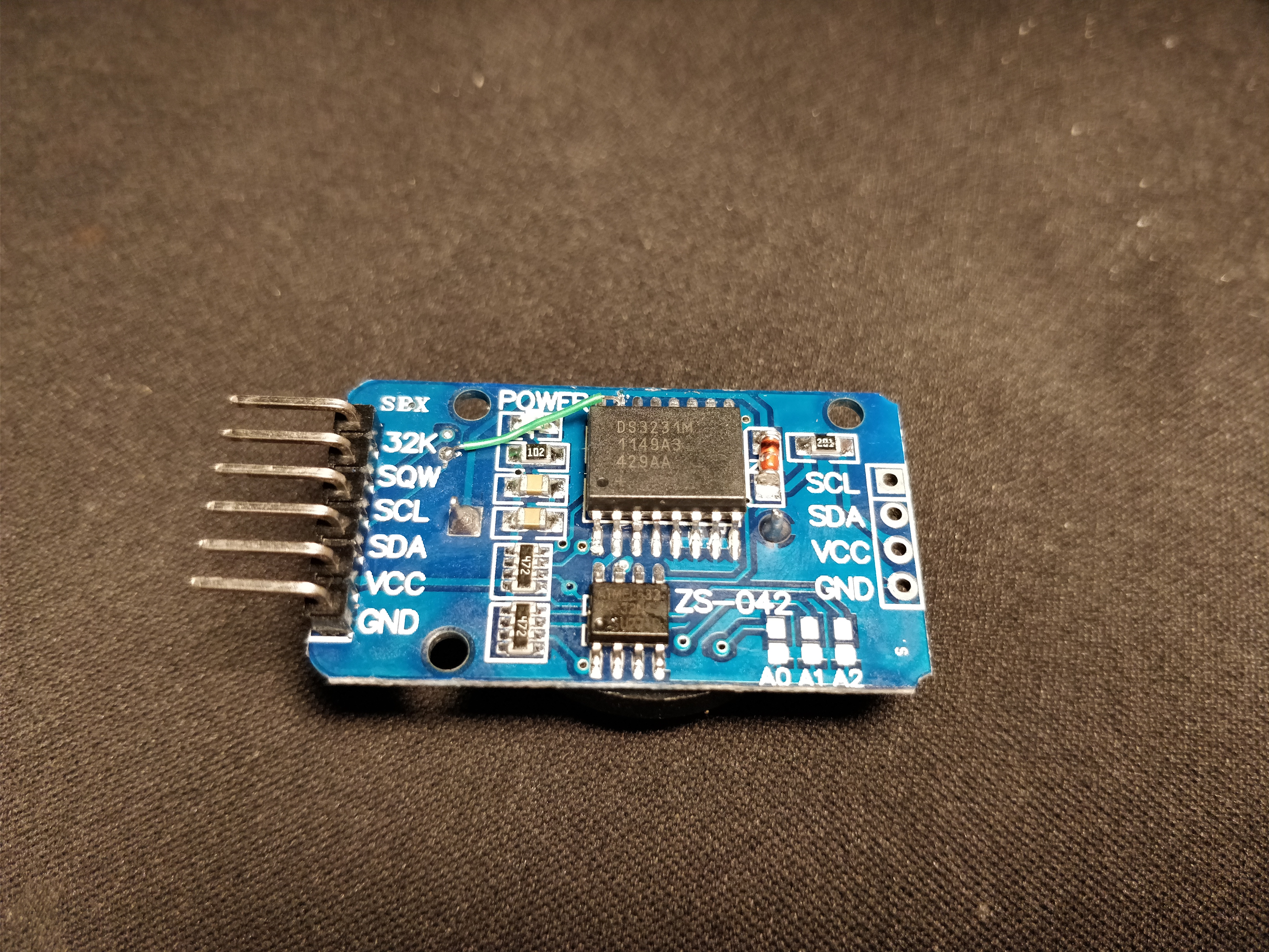
That I received a board with a wrong chip turned out to be fortuitous, since I was able to desolder the incorrect chip (at the cost of lifting one pad, hence the bodge wire in the photo below) and replace it with one of the “free samples” of genuine DS3231Ms I ordered from Maxim (many thanks to Maxim for offering such samples with minimal hassle) without having to waste a working chip. Note that although I placed the order for the free sample in August of 2017, the date code on the genuine chip pictured above is from December of 2011. Obviously Maxim keeps an inventory of chips in storage, presumably to have a buffer for spikes in demand.
The genuine Maxim chips (both the one I soldered to the board, as well as the second one I received but haven’t put on a board) both meet the datasheet specs for 1 Hz stability. So do the eBay-sourced ones. The laser markings on the packages are nearly indistinguishable, and all the eBay-sourced ones appear to be authentic Maxim chips.
After doing some tests with the M variants, two major differences between the two variants became clear. These are detailed in the respective datasheets (available here for the DS3231, and here for the DS3231M), but are a bit subtle and may be, as Dave Jones says, a “trap for young players”. Thus, I felt I should explicitly mention them here.
Here we go:
1. The DS3231 can be used as both an RTC and a TCXO but the DS3231M is only an RTC.
This is actually mentioned in the title of each chip in their datasheets, with the DS3231 described as an “Extremely Accurate I2C-Integrated RTC/TCXO/Crystal”, while the DS3231M is described as a “+/- 5 ppm, I2C Real-Time Clock”.
Why is this so? Let’s take a look at the block diagrams from the datasheet to find out. First, here’s the crystal-based DS3231:
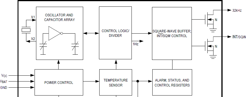
The crystal, which is integrated into the package itself, is connected to the oscillator circuit and array of capacitors which can be switched in and out to steer the frequency.
The output of the oscillator is sent to the control system that, after reading the temperature from the temperature sensor, determines the number of capacitors to switch into the circuit to compensate for any changes in temperature. A divider in the control system outputs both a 1 Hz signal which is used internally for timekeeping, as well as other signals which are used in the “square-wave buffer; INT#/SQW control” block. Critically, both of these outputs are temperature compensated.
The “square-wave buffer; INT#/SQW control” block has two external outputs, both open drain (and thus requiring external pullup resistors): the 32.768 kHz output and a user-programmable interrupt (e.g. for an alarm) or square wave (which is programmable to produce either 1 Hz, 1.024 kHz, 4.096 kHz, or 8.192 kHz signals) output.
In short, one can use the “32 kHz” pin to measure the actual, temperature compensated frequency of the crystal oscillator, as well as using the “INT#/SQW” pin to output a temperature compensated signal either at 1 Hz or one of several fixed frequencies.
Keep in mind the following caveat from Maxim (personal email from one of their application engineers):
The DS3231SN# is a crystal based RTC whose 32kHz output is temperature compensated. So depending on the temperature we will adjust the internal capacitive load to maintain a consistent 32kHz frequency across temperature. However, the DS3231 series is not intended to be used as a 32kHz reference as the design is strictly focused on creating the most accurate 1Hz signal to drive the RTC.
Seems reasonable to me: the DS3231 is primarily focused on timekeeping, and the 32 kHz output is a nice bonus. Although the 32 kHz output will be continuous (i.e., it won’t skip or add extra pulses), the frequency output is only corrected for temperature variations every 64 seconds and so may drift a bit during that time. When the temperature conversion and correction happens, there may be a sharp, distinct change in frequency. For systems that require smooth changes in frequency, using a DS3231 as a clock source or frequency standard might not be the best option. For other purposes though, it may work reasonably well. I use mine for driving AVR microcontrollers at low speed, and this works fine.
Compare the above diagram with that for the DS3231M:
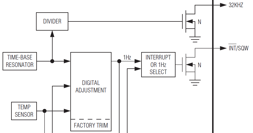
In lieu of a crystal, the DS3231M’s MEMS “time-base resonator” oscillates at a high-but-unspecified frequency. The resonator signal is sent to both a divider and to the digital adjustment block. Note that the temperature sensor is connected to the digital adjustment block (but, critically, not the divider that drives the 32 kHz output), which in turn outputs a temperature compensated 1 Hz signal to the timekeeping block (out of view above) and to the INT#/SQW output pin which can produce a 1 Hz signal.
The 32 kHz output of the DS3231M is not temperature compensated, while the 1 Hz INT#/SQW output is.
The 1 Hz signal has a specified stability of 5 ppm, but the 32 kHz signal can vary by up to +/- 2.5%. Yikes.
If you have a frequency counter or an oscilloscope with a stable reference, you can see the difference between the two chips by probing the 32 kHz output (with a proper pullup resistor) and then touching the chip with your finger to gently warm it. The DS3231’s output frequency will slowly change and, after up to 64 seconds, the chip will compensate and the frequency will stabilize again. The DS3231M’s output frequency will change dramatically since the temperature coefficient of a MEMS oscillator is significantly higher than that of a crystal, though the temperature coefficient of the MEMS oscillator is not specified in the datasheet.
I have no idea why they designed the chip this way, but it is what it is. It’d be nice if a later revision to the DS3231M offered a temperature compensated 32 kHz output.
This brings us to the second point.
2. The DS3231 can output one of several frequencies or an interrupt on the INT#/SQW pin, but the DS3231M can only output a 1 Hz signal (or an interrupt).
By writing to bits 3 (Rate Select 1, RS1) and 4 (RS2) and setting bit 2 (Interrupt Control, INTCN) to 0 in the control register (0x0E) of the DS3231, a square wave at either 1 Hz, 1.024 kHz, 4.096 kHz, or 8.192 kHz will be output on the INT#/SQW pin.
On the DS3231M, the RS1/RS2 bits are not used and have no effect. When INTCN is set to 0, the INT#/SQW pin outputs a 1 Hz signal. No other frequency options are available.
The INT#/SQW outputs of both chips are temperature compensated.
So far, these are the only two major differences I’ve found between the M and non-M variants. Are you aware of any more? Do you have any idea why Maxim would choose not to have the 32 kHz output of the DS3231M be temperature compensated? Why would they not allow for several user-selectable output frequencies and only allow the user to select the 1 Hz output? If you know, please comment!
Hello, from Atlantic Canada.
That was a great article, Pete, and I thank you for sharing it.
I just received 8 of those little “DS3231 for PI” boards (the very small board, with the five pin header connector) and found that 7 of them were the “M” type, and only one was a “SN”.
So, just to let you know, I referenced this blog article of yours in a “review” that I just submitted on Amazon.ca, to let other buyers know they may be getting something other than they expected. It looks like the Amazon folks vet or moderate review postings, because their web response said that it might take a few days for the review to appear. The product page is at:
https://www.amazon.ca/gp/product/B07GRRBB8B/ref=ppx_yo_dt_b_asin_title_o00_s00?ie=UTF8&psc=1
If they do post it, have a look and let me know if I have made any error or if I have misrepresented you in any way, and I shall endeavour to fix it.
Thanks and very best regards,
“Steddy”
Hi Steddy,
My pleasure! Thank you for your kind words, for reading the article, and taking the time to comment.
I have several of those boards with the SN chip (most without the batteries — I just soldered on a supercapacitor and a diode for charging or a CR2032 holder) and they work really well. I’m sure the M ones will work fine for you as well. Rumors have it that the Chinese vendors that supply such “gray market” vendors have run low on/out of the SN models and so are switching to the M models. For the Pi it shouldn’t matter since you’re not likely to need the regulated 32kHz output signal.
The review at Amazon hasn’t shown up yet, but I’ll check periodically and see it when it does. I look forward to hearing your experience with them.
It turns out that, for some reason, Amazon does not like it when reviewers quote web URLs and they will not post it. Some time later, I will re-write it and re-submit.
The review is up on the Amazon product page, now. I had to change it to remove the URL to your site here, as somebody at Amazon apparently thinks that putting URL references in reviews is some kind of evil. So I made a more oblique reference to here (and to another page at Instructables.com), without actually quoting the URLs or site names. I referenced you as “… someone whose pseudonym is ‘HeyPete'”. 😉
I looked it over and things look good! Thanks for the mention. 🙂
I ended up here after ordering two of those RPi RTCs from a popular ebay seller and one of them was a DS3231M
This is good info. Looks like the DS3231M is not useless at all, just not as good for some uses.
I’d be very interested in anyone who had testing data of their accuracy. I know it’s very variable on individual unit and on other environmental factors not to mention temp. I just have an unsatiable appetite for that sort of thing.
For the battery backup I’m thinking soldering up a 2xAAA holder, of which I have a few already so not a big deal even though AAAs would be overkill for that. The >2.4V at low current from that over most of their discharge life I hope should be fine.
Thanks for stopping by!
The DS3231M model is perfectly suitable for most uses for which an RTC would be handy, and keeps remarkably good time (5 ppm is really good). I just wish it had a temperature compensated frequency output like the non-M variant, but alas.
I did do some earlier accuracy measurements with M and non-M variants. The results are here, but can basically be summed up as “they meet the advertised spec”. Note that such measurements were several years ago and I have no idea if the chips being sold through eBay and other gray market sources would still meet those results. I have no reason to suspect otherwise, but something to keep in mind.
AAA batteries would do fine for a backup and would be quite overkill in terms of capacity. But my philosophy is “overkill is barely enough”. 😛 My only concern would be that alkaline cells would leak or corrode over time (I have really bad luck with leaky batteries), particularly if they ever run low. Coin cell batteries like CR2032s are small, cheap, last for a decade, and don’t leak, so that makes them more appealing for me. But AAAs are perfectly fine as well.
Hi!
Thanks for the explanation. I used DS1307 (5v) and DS1338z (3v3) and most of the time, I’ve controlled the crystal using 32kHz output. It helps me quickly ensure that osc is running and check its frequency.
But the first (and yet single) DS3231SN, I’ve got some time ago from the local supplier, shows awful 4 minutes per day runout and very unpleasant frequency at 32kHz output. I’ve double checked the layout, datasheet requirements and code and don’t found anything wrong. At least DS1307/1338 was running with the same (I know the diffs!) code and at the same conditions well, of course with their own declared accuracy and temperature (in)stability.
So, I wait till some another DS3231M arrived from China and try to check the same 32kHz to ensure their accuracy. I was really frustrated, as the frequency at 27.0C was 32700Hz, at 70C ~ 32680Hz and at 0C – 32730Hz. Where is the temp compensation?! Where is the stable 32768Hz, corrected every second?!
But your explanation clearly enlightens different approaches used to compensate frequency between DS3231SN and DS3231M. Thanks!
That sounds like you have either a defective or fake chip. I’m curious what your results are with other chips. Hopefully they work better!
Thanks for the elaboration. Until came across this article, I was not aware of the two distinct type DS3231 RTC chip. But, was puzzled, why the newly built digital clock (DS3231M RTC) drifts in short period of time, whilst a four year old clock made around DS3231SN keeping time (almost) perfectly.
Replaced the “M” chip with “SN” has solved my problem.
Thank you for useful information.
I have been testing ds3231 , and noticed bad accuracy chip is existing.
After reading your article, I understood what is happening.
I’ve posted a link from my DS3231 article. (sorry all written in japanese)
http://radiopench.blog96.fc2.com/blog-entry-950.html
My pleasure! I’m glad you found the information useful, and thank you for commenting.
It’s very interesting that you had an “N”-marked model. That’s very odd, as there’s nothing with that suffix on the Maxim website. I suspect it too is fake, or at the very least re-marked. How good is its accuracy?
The “M”-marked chips you tested have an accuracy well within their 5ppm spec: you stated they were off by 10 seconds after one month. That’s about 3.8 ppm. Not bad.
I looked over your posting and it looks excellent, and is easily translated by Google Translate.
I came across this article while trying to understand why three Chinese IN-12 Nixie clocks I purchased recently keep such lousy time. One loses about 10 minutes every 24 hours. Another loses 2 minutes or so every 24 hours. The third varies by 12 seconds or so in a day. All show some kind of issues with temperature. I was refunded most of my money on them and was told to keep them.
I was curious as to why these clocks performed so badly where other similar clocks worked perfectly fine. I noticed that all of the clocks use a DS3231M. On the three IN-12 clocks I noted the markings on the chip are all identical:
DS3231M
1125A1
109AD
Not quite sure how to read the date but I am assuming 2011 as the year of manufacture. On a different clock, designed for QS30/ZM102x Nixie tubes that loses about 1 second every three weeks, I found the chip marked:
DS3231M
1221A3
007AA
In this case, I am assuming 2012 as the year of manufacture. Another clock board has a larger DS3231SN and shows no timing issues.
It would appear to me that the lot marked 1125A1 is either defective or counterfeit. If I had the ability to work with SMD components, I would try replacing the original DS3231M’s with newer quality verified chips and see if that fixes the problem. The really bad clocks I will file away if/until I find a way to try and repair them.
Interesting, thanks for the info. The 1221A3 one you have seems to be a keeper: that’s holding ~0.5 ppm, which is outstanding.
Too bad about the 1125A1 chips. Fortunately, SMD work isn’t really that bad if you’ve got a soldering iron and a bit of time — by globbing on solder and bridging the pins on each respective side of the chip together with one big blob of molten solder and rapidly alternating the iron between sides so both sides stay molten you can usually pop the chip up pretty easily, then use solder wick to clean up the pads. Just be careful not to lift a pad when it’s too hot. You might also try cutting the legs of the bad chips off using diagonal cutters and then desoldering the stumps left on the board (careful: I lifted a pad doing this).
Once the pads are clean it’s pretty straightforward to SMD solder with just an iron: get the chip lined up, tack down a corner with a bit of solder, flux all the pins, then run a blob of solder across all of them with the iron. You’ll likely have bridges between pins, so get those with some wick. There’s good YouTube videos on the technique if you’re not familiar.
In the event that repairing them turns out to be infeasible, I’d be interested in buying one of the bad ones from you and seeing if I can get it working. My email is pete@heypete.com.
“Do you have any idea why Maxim would choose not to have the 32 kHz output of the DS3231M be temperature compensated? Why would they not allow for several user-selectable output frequencies and only allow the user to select the 1 Hz output?”
Maybe their MEMS design cannot be tuned with capacitors and/or it would be cost prohibitive?
If they run the 32KHz in to a counter, it’s easy enough to increment or decrement the count based on the temperature compensation circuit. The 1Hz would be nice and clean.
However, to output a compensated 32KHz in that scenario, they’d need to insert extra pulses or eliminate some; and over a short window measurement that would introduce a large timing error.
Good thinking, I like it! I’m pretty sure they’re not steering the oscillator itself; I took apart a DS3231M and there’s no tuning capacitors.
There is another difference, a bad one..
When the device is running on timekeeping current (IBATt), the /INT line cannot function as an alarm. Unfortunately I was using this alarm output to wake up my device.
Great article.
I recall the golden days [DS1302+crystal] and being happy with +- 10ppm.
After needing an RTC, I bought a module with that DS3231xx that turned out to be an “M”. So, after setting the time (with aging register 0x00), I let it set for a couple weeks. Then compared again with time.gov… that made it easy to calculate the aging 0xDA, set time and again set aside for a couple weeks, and it matched world time visually perfectly. The MEMS + proper aging value, can get within a fraction of a ppm! [but not seen on 32.768Khz pin]
While looking for that RTC, somebody was selling a box DS3231 modules. Seller didn’t say how many were in the box… but it looked like a lot. Opening bid $35, and I won!. Box arrived with 132 modules with batteries. – some with the LiR2032. By far, the majority of them were SN, some were M and some were N!
What to do with 132 modules, we will see.
Articles like this are making the internet great. I had a question which I expected nobody can answer, and voila, here are all the answers and more.
Just want to give my superfluous cents: got a sixpack with modules showing the DS3231SN. Turned out they reset their time to jan 1st 200 after a few minutes without VCC, even with a brand new CR2032 cell for buffering.
I ordered at a german reseller, but they obviously use chinese sources. These chinese fakers are a curse. If there would be only one trustworthy seller with moderate pricing. Does anyone know a source delivering to europe? (Mouser, RS, Farnell and all the vampires are not an option.)